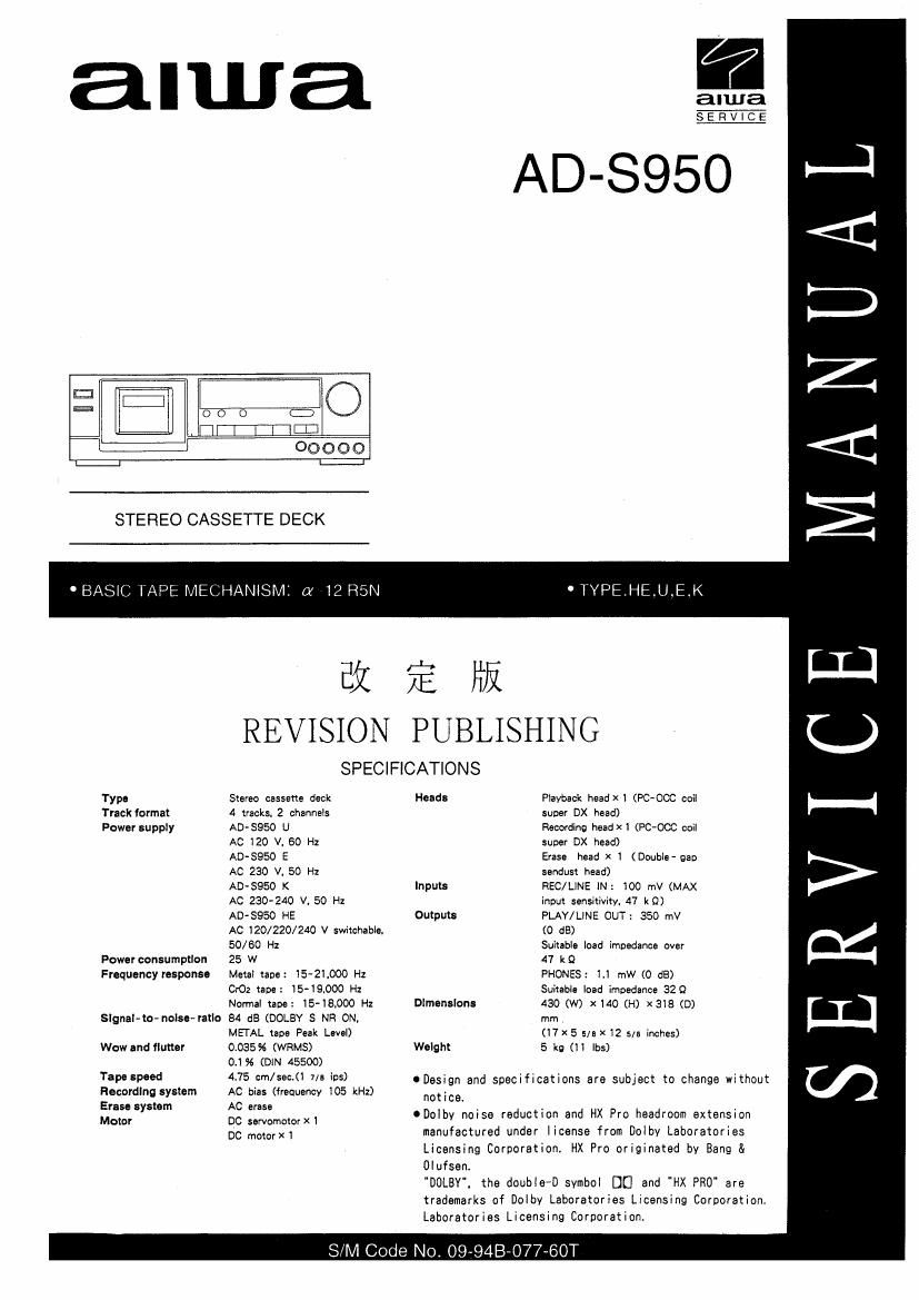
Aiwa AD S950 Service Manual

This is the 22 pages manual for Aiwa AD S950 Service Manual.
Read or download the pdf for free. If you want to contribute, please mail your pdfs to info@audioservicemanuals.com.

Page: 1 / 22
left right
Aiwa AD S950 Service Manual

Extracted text from Aiwa AD S950 Service Manual (Ocr-read)


Page 1

alwa

alwa
SERVICE

AD-SQSO

E: f-JI
aI I 000 :30
I

TITI-I'T'ICEI
00000

STEREO CASSETTE DECK

' BASIC TAPE MECHANISM: a 12 RSN ' TYPE.HE.U.E.K

65: % Iii
REVISION PUBLISHING

SPECIFICATIONS
Typa Sumo oassme deck Heads Playback headx I (PC~OCC coii
Track format 4 tracks 2 channais super DX head)
Power supply AD»5950 U Recording headXI (PC-00C ccii
AC 120 V, 60 H1 suoer DX head)
AD-SQSO E Erasa head X I (Doubia 9w
AC 230 V. 50 Hz sendust head)
AID-$950 K Inputs REC/LINE IN : IOO mV (MAX
AC 230- 240 V. 50 Hz inom sensitivity. 47 k9)
ADSSSO HE Outputs PLAY/LINE OUT: 350 mV
AC 120/220/240 V switchabiar (D 68)
50/60 Hz Suitabie load impedance over
Powerconsumption 25 W 41' k9

Frequency response

Metal tape: 15-21000 H1
CrO: tape: 15-13000 Hz

PHONES: I.I mW (0 d8)
Suhable Ioad impedance 329

Normal rape: 15-18900 Hz Dimensions 430 (W) x140 (H) x318 (D)
Slgnal-tn- noinevratlo 84 dB (DOLBY S NR 0N, mm

MEDAL ups Peak Lavei) (I7x 5 5m x 12 5/5 inches)
Wow and flutter 0.035% (WRMS) Weight 5 kg (Ii lbs)

O.I 56 (DIN 45500)

.._J
<1:
:3
Z
<1:
2
L11
C.)
i--i
>
Q6
[.11
V)

Tape Speed 4.75 cm/sec-(I 7/: ins) ODesign and specifications are subject to change without
Recording system AC bias (frequency 105 kHz) notice

Erase system AC erase ' , , .
Motor QC servomoiorxi oDoIby noise reduction and HX Pro headroom extanSIon

manufactured under license from Dolby Laboratories
Licensing Corporation HX Pro originated hv Bang &
Oqusen.

"DOLEY. the doubIe-D svmbol DE] and "HX PRO' are
trademarks of Doibv Laboratories Licensing Corporation.
Laboratories Licensing Corporation.

DC mmar x 1

SIM Code No. OQ-94B-O77-60T

Page 2

DISASSEMBLY INSTRUCTIONS

1.Noles on replacing the Power Transformer":
When replacing the "Power Transformer". attach a
'Plate, Shield" to the specifed position to conform to
the safety standard (spacing).
1) Attach the shield plate with adhesive tape while
aligning it to portion @, At this time. apply
a threadlocking adhesive to it.

I ACCESSORIES/PACKAGE LIST

Align this to the edge 01 the \ianslovmevs core band.

Plate. Shield


Apply threadlockinn adhesive.

Align this 0 the bottom at the cove band. '
Power Transtormer

DESCRIPTION TWWT'C 3 filth \mli REFERENCE NAME LIST

If can't understand for Description please kindly refer to REFERENCE NAME LXST".

éfifibc(i-élflo

REF. N0 PART NO. hall DESCRIPTION
N i
1 83-DSl~901-019 IB, EGFS|C(S) (EXCEPT U)
2 83-031 >902>019 IB. ESHS) (U)
3 83>DSZ-631-019 RC. RC-SIOB
4 87-009-725-019 PLUG.ADPTR |R40(HE>
5 87-034-786-019 CORD PIN 1890760