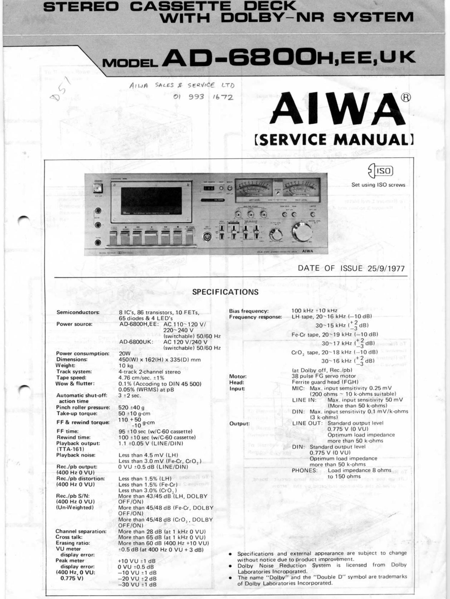
Aiwa AD 6800 Service Manual

This is the 23 pages manual for Aiwa AD 6800 Service Manual.
Read or download the pdf for free. If you want to contribute, please mail your pdfs to info@audioservicemanuals.com.

Page: 1 / 23
left right
Aiwa AD 6800 Service Manual

Extracted text from Aiwa AD 6800 Service Manual (Ocr-read)


Page 2

moon AD-fiBflflH,EE,UK AIWA AIWA MODEL AD-BBIIOH,EE,UK

DISASSEMBLY INSTRUCTIONS

TO RUN". Case To Remove 30° 0°" To Remove Power/OSC Circuit Board
Remove 5 screws. Remove 6 SC'WVS- Remove 2 screws.

y'a-ewua)

/

Screw. loo panel
Screw. Too panel /


U+3-6

4?

i'rrnga. i-

M 1""

To Remove Filter Circuit Board
Remove 2 screws.

Screw. Top panel

M

.l
To Remove Meter Amp./Test Head Amp. Circuit Board
To Remove Level Meter To Remove Front Panel 1) Remove 2 washers and nuts or the wolume shafts,
1 d 4 ts Remove 6 screws and knobs. 2) Remove 4 selector swutch screws.
) R°m°V° 3 WW 0" m; . 3) Remove 3 DIN jack screws.
. » vs+ 2-6 . R f H 4) Remove 2 circuit board screws. %

Nate: When removing the DIN jack, pull the DIN holder in
the direction indicated by the arrow and remove.

vVISiJ a

as
To Remove Stop Mutiny Circuit Board
Remove mounting screw.
l
i:
t , .
l VSLti2.6-4
To Remove Main Circuit Board
l
SGT?V;: it??? and 4 connectors _ . _ "5 To Remove Switch Circuit Board
To Remove REC/LED Circuit rd ° °' '. connectors 3" located '" different c°""°°""9 . 1) Remove 3 push rod stoppers and draw in the direction
80' positions according to the model since "10V are l . -
Remove 2 screws. . _ . w; indicated by the arrows.
used to edpust the bras current. Therefore, check in .
To no" Bias Circuit 80.". ' 4m 2) Remove 4 screws and connector, and the swrtch
the connecting positions and always connect to l
Remove3 nuts. ' _ . _ . it circuit board can be removed it it is drawn in the
their original positions when reconnecting. . . . .
,REC'LED Cur-m Board 7 direction indicated by the arrow.

To Remove Motor Circuit Board
.- Remove 2 screws.

To Remove CrO: Auto Circuit Board
Remove mounting screws.

1, To Remove Auto-StoplTimer Start Circuit Board.
A Remove 4 screws.

.

7.1"

BIAS Circuit Board

-

PK: >

To Remove Room Lamp Circuit Board
Lift up the right side of the room lamp circuit board,

and draw in the direction indicated by the arrow. i |

To Remove Mechanism uéiflm- 4
Remove 4 screws and counter belt.

To Remove Relay Circuit Board
Remove 2 screws and 2 nylon rivets.


U.+i2.6-l MOYOR Cuciul Board

wkvsur 3 - s
. I

VSiM-s a

lafiflc r: RiQQ-L_' *'

i

\ N : .
\ 4- N
\.
\S - A u + 3 - 4
vs J/l/V AUTO srorwmcn sum
3+: 3 _. 6 _. \. , _ CirCuu Board
\? \ -- /- CrO: wt circuit Bow!
8

RELAY Circuit Board