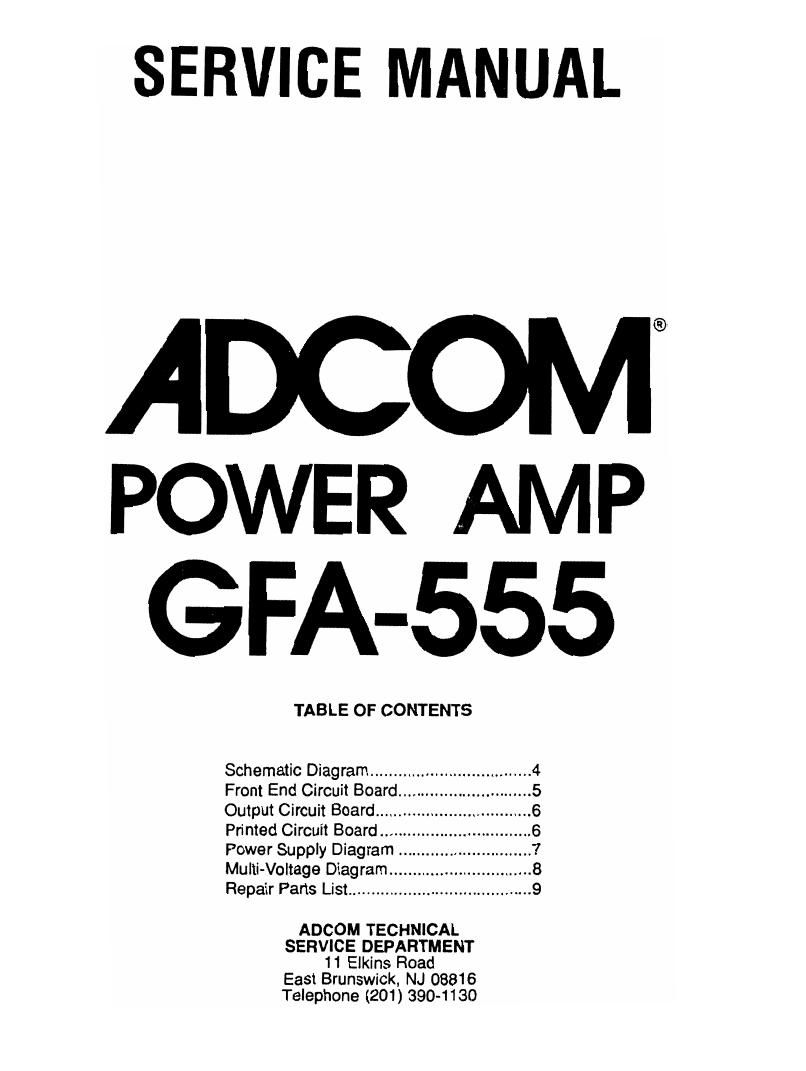
Adcom GFA 555 Service Manual

This is the 10 pages manual for Adcom GFA 555 Service Manual.
Read or download the pdf for free. If you want to contribute, please mail your pdfs to info@audioservicemanuals.com.

Page: 1 / 10
left right
Adcom GFA 555 Service Manual

Extracted text from Adcom GFA 555 Service Manual (Ocr-read)


Page 1

SERVICE MANUAL

ADCOM

POWER AMP
GFA-555

TABLE OF CONTENTS
Schematic Diagram ................................... 4
Front End Circuit Board. ........ 5
Output Circuit Board .............. 6
Printed Circuit Board ................ 6
Power Supply Diagram ........ 7
Muiti-Voltage Diagram ...... ....8
Repair Parts List ........................................ 9

ADCOM TECHNICAL
SERVICE DEPARTMENT
11 Elkins Road
East Brunswick, NJ 08816
Telephone (201) 390-1 130

Page 2

ADCOM GFA-555 Service Manual

Introduction

This repair manual is intended to assist qualified technical personnel in
verifying performance, adjusting, and repairing the ADCOM model GFA-555
power amplifier. The procedures described here are not intended for consumers
or persons not familiar with the appropriate safety procedures.

Warning: Procedures described herein require working with
hazardous voltage potentials, and are intended for qualified
personnel only.

Circuit Description

The ADCOM GFA-555 is a stereo power amplifier rated at ZOO-watts-per-
channel into 8 ohms and capable of greater than 20-amps output into low
impedance loads. The amplifier employs a discrete Class-A voltage-gain stage
(front end) which amplifies the input signal up to the voltage required at the
output of the amplifier. This high-voltage signal drives the high-current
Darlington-follower output stage which amplifies the current by a factor of
about 2,000

Referring to the accompanying schematic, the input signal passes through
network R1 and C1 which provides a radio-frequency rolloff above 500 kHz. R2
provides a DC source impedance in the absence of any signal source. Input
amplification and feedback occur in Q1 and Q2, a standard differential pair
input stage, with R3 and R4 providing local feedback for open loop gain control.
The next amplification is provided by Q7 and Q8 used to limit the possible
current flow when the voltage drop across R8 exceeds 0.6 volts, or about 20
milliamps. The signal comes out of the collector of Q7 at full output voltage. C2
is used to balance the slew rate of the positive swing to the rate of the negative
swing, and C4 provides a secondary high-frequency feedback loop to the input
stage, allowing the input stage to ignore the output stage lag at very high
frequencies, providing additional stability.

Feedback is provided from the output to base of Q2 by the network R6, R5,
and C3. CB provides rolloff below 3 Hz.

The gain stages of Q1 , Q2, and Q7 are biased into single-ended Class-A
mode by the circuitry of RIO-11, R13-16, D3-D6, and Q3, 4, and 6. D3 and D4
forward-bias transistor Q6 at 1.3 volts from current provided through R13.
This creates about 0.6 volts across R11 so that Q6 sources about 1 milliamp
through thermostat T1. This current biases the diodes D5-6 to 1.3 volts,
causing 2 milliamps constant current sourced from Q3 for the input pair, and 4
milliamps constant current sourced from Q4 for the secondary gain stage of Q7.
Between the collectors of Q4 and Q7 is the bias network which biases the

Page 1