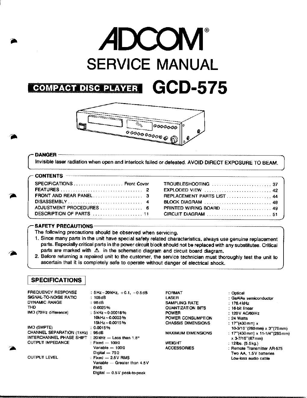
Adcom gcd 575 service manual

This is the 55 pages manual for adcom gcd 575 service manual.
Read or download the pdf for free. If you want to contribute, please mail your pdfs to info@audioservicemanuals.com.

Page: 1 / 55
left right
adcom gcd 575 service manual

Extracted text from adcom gcd 575 service manual (Ocr-read)


Page 1

3.

SERVICE MANUAL
GOD-575

SPECIFICATIONS
FREQUENCY RESPONSE : 5Hz~20kHz, +0.1. 415.15
SlGNAL-TO-NOISE RATIO : 10503
DYNAMIC RANGE : 93cm
THD : 0002504,

IMD (TOHz ditterence)

IMD (SMPTE) :
CHANNEL SEPARATION (1 kHz) :
INTERCHANNEL PHASE SH|FT
OUTPUT IMPEDANCE

OUTPUT LEVEL

2 5kHz~0t0001B°/o

10kHz - 000030/n
15kHz ~Di0015%
0.00!5%

95GB

: 20 kHz - Less than 13°
: Fixed 7 1009

Variable - 1009
Digital - 759

: Fixed - 2.5V RMS

Variable 7 Greater than 4.5V
RMS
Digital - 05V peek-topaak

,- DANGER 1
Invisible laser radiation when open and interlock tailed ordeleated. AVOID DIRECT EXPOSURE TO BEAM.

L J
(- CONTENTS w \
SPECFFICATIONS .................... Front Cover TROUBLESHOOTING ....................... 37
FEATURES ................................. 2 EXPLODED VIEW ......................... 42
FRONT AND REAR PANEL, .................. 3 REPLACEMENT PARTS LIST .................. 44
DISASSEMBLY .............................. 4 BLOCK DIAGRAM ........................... 48
ADJUSTMENT PROCEDURES ................. 6 PRINTED WIRING BOARD .................... 49

DESCRIPTION OF PARTS .................... 11 CIRCUIT DIAGRAM .......................... 51 J
SAFETY PRECAUTIONS \

The following precautions should be observed when servicing.

1t Since many parts in the unit have special safety related characteristics. always use genuine replacement
parts. Especially critical parts in the power circuit block should not be replaced with any substitutes. Critical
parts are marked with A in the schematic diagram and circuit board diagram.

2 Before returning a repaired unit to the customer. the service technician must thoroughly test the unit to
ascertain that it is completely safe to Operate without danger of electrical shock.

_)

FORMAT : Optical

LASER : GaAIAs semiconductor
SAMPLING RATE : 176.4 kHz
QUANTIZATION BITS : 16-bit linear

POWER 1 120V ACISOHZ
POWER CONSUMPTION I 24 Watts

CHASSIS DIMENSIONS ; 17'1430mm) x

MAXIMUM DIMENSIONS

WEIGHT
ACCESSORIES

1W16"(260mm)x 3"(76mm)

: 17"(430mm) x 11-1!4"(285mm)

x 3-7/16"(87 mm)

: 12lbs. (5.5kg)
: Remote Transmitter AIR-575

Two AA, 1.5V batteries
Low-loss audio cable

Page 2

CAUTIONS REGARDING HANDLING OF THE LASER

This device uses an invisible (near-infrared) laser to pick up signals recorded on the disc. Laser radiation does
not leak from the unit during normal operation However when the top cover is removed care must be taken
to avoid looking directly at the beam emitted by the laser. The laser 5 maximum rated power output from the
lens Is 0. 4mW However, when this' Is focused the power reaches 1. 3 x 10 mW/cm. Beside the laser diode,
the pickup ass' y contains optical components such as the beam splitter, and lens, etc., as well as a 6-way
photo diode, and is precisely constructed. Please do not disassemble the pickup ass'y as the optical compo-
nents are very easily damaged by dust and dirt and the laser diode contains dangerous substances.

Check that exposed parts are properly insulated from
the supply circuit before returning the instrument
repaired to the customer.

' Checking method
Power switch is set to ON.
Next, measure the resistance value between both
poles at the AC power supply plug, and the outside,
ground connection of the RCA jacks on the rear
panel. The resistance value must be 500 kit or more.

FEATU RES

I Very-low-impedance output (1009)

I Dual digital-to-analog, 16-bit linear converters

I Triple-beam laser format

I 176.4kHz, lour-timesoversampling tillers

I Low-group-delay. digital and innovative analog filters

I Unique, selectable Analog Frequency/Phase Contour-
ing circuitry

I High-grade-contact muting relays

I Direct-coupled audio amplifiers employ very last, linear-
gain semiconductors with circuitry based on the
(EFF-555

I OCL outputs with virtually no DC offset

I Fixed and variable outputs usable simultaneously

I Direct digital output

I Very-high-quality variable headphone output

INSTRUMENT

(Exposed PW)

\

'00"

Insulation tester

I Selectable absolute polarity switch

I Outstanding interchannel phase coherence

I Reversible cast-metal leet with built~in iso-points

I Front-drawer loading

I Plays 3-inch CDs with no adaptor required

I Programs up to 24 tracks in any sequence

I Repeats disc, track, program or any selected sequence
or phrase

I Fast-lorward and last-reverse scans are audible

I Displays simultaneously total tracks up to 20, track be-
ing played, programmed tracks, tracks to be played

I Timer displays elapsed time 01 track being played. to-
tal time elapsed on disc, time remaining on track, time
remaining on disc