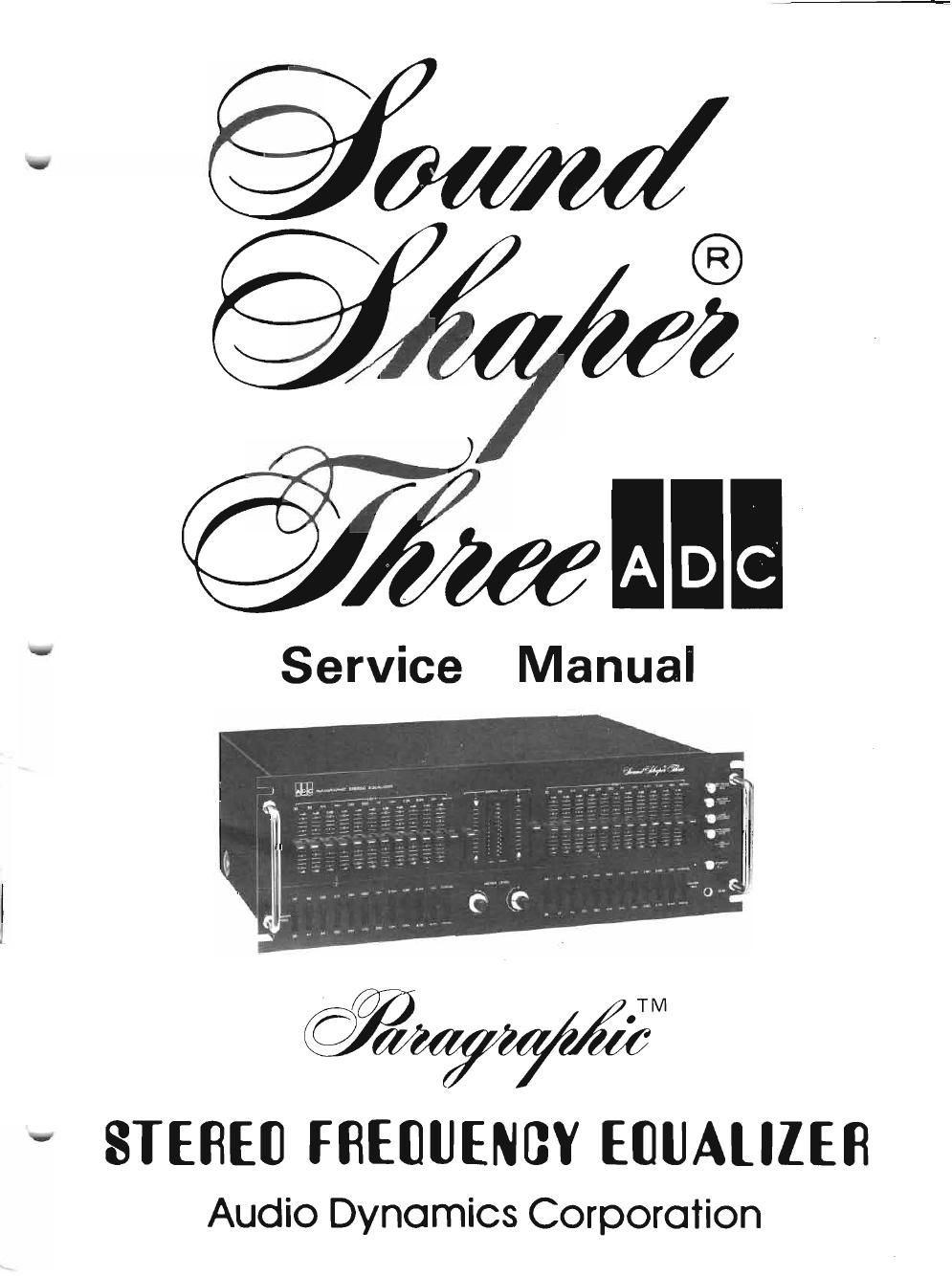
Adc soundshaper three service manual

This is the 40 pages manual for adc soundshaper three service manual.
Read or download the pdf for free. If you want to contribute, please mail your pdfs to info@audioservicemanuals.com.

Page: 1 / 40
left right
adc soundshaper three service manual

Extracted text from adc soundshaper three service manual (Ocr-read)


Page 1

~---------------CONTENTS----------------~ PAGE ELECTRICAL PERFORMANCE SPECIFICATIONS 3 CI RCUIT DESCRiPTION ,4-9 SWITCH FUNCTIONS 0-12 DISASSEMBLY INSTRUCTIONS 2 BLOCK DIAGRAM . ADJUSTMENT PROCEDURES '- CALIBRATOR SCHEMATIC.................................. . . . . .. .. - TROUBLESHOOTING - SYMPTOM· CAUSE/REMEDY i7- ':' AMP P. C. B. (TOP & BOTTOM VI EWS) . . . . . . . . . . . . . . . . . . . . . . . . . . . . . . . . . .. ~ POWER SUPPLY & METER P. C. B. (TOP & BOTTOM VI EWS) ~ SWITCH (L) P. c. B. (TOP & BOTTOM VIEWS) 21 SWITCH (R) P. c. B. (ROP & BOTTOM VIEWS) 22 SLIDE VOLUME (L) P. c. B. (TOP & BOTTOM VIEWS) 23 SLIDE VOLUME (R) P. C. B. (TOP & BOTTOM VIEWS) 24 ELECTRICAL PARTS LIST 25-34 EXPLODED VIEW PARTS LIST 35-36 MISCELLANEOUS PARTS LIST 37 SCHEMATIC DIAGRAM 38-39 EXPLODED VIEW 40-41 -2-

Page 2

- 3 - ELECTRICALPERFORMANCE SPECIFICATIONS (Unit)(Nominal) (Limit) Frequency response at flat position, I nput level =0.775 V (Hz) 5-100 K~U dB 5-100 K~?:5 dB Control Frequency accuracy at 26, 32, 39 Hz (%) ±5 ±10 at 47, 56, 68 Hz (%) ±5 ±10 at 84,100,120 Hz (%) ±5 ±10 at 150,180,215 Hz (%) ±5 ±10 at 260,320,390 Hz (%) ±5 ±10 at 470, 560, 680 Hz (%) ±5 ±10 at 840, 1 K, 1.2 KHz (%) ±5 ±10 at 1.5 K, 1.8 K, 2.15 KHz (%) ±2.5 ± 5 at 2.6 K, 3.2 K, 3.9 KHz (%) ±2.5 ± 5 at 4.7 K, 5.6 K, 6.8 KHz (%) ±2.5 ± 5 at 8.4 K, 10 K, 12 KHz (%) ±2.5 ± 5 at 15 K, 18 K, 21.5 KHz (%) ±2.5 ± 5 (Output level =0.775 V) Control range at 0.775 V Input (dB) +13.5+12~~·5 -13.5 -12~~.5 Harmonic Distortion at 1 V Output from 20 Hz to 20 KHz (%) 0.018 0.04 Hum and Noise ratio at 1 V Output (dB) 9085 (I nput shorted) (I H FA) Dynamic Range into 10 Kn load (V/rms) 109 (All Controls should be Flat) Input Impedance (Kn)75 Output Impedance at 1 KHz (n)10 Intermodulation Distortion at 1 V Output, 70/70 KHz at 4/1 ratio (%) 0.02 0.05 Meter tolerance (F requency at 1 KHz) at+12dBpoint (dB)±0.5±1.0 at OdBpoint (dB)±0.5±1.0 at-12dBpoint (dB)±0.5±1.0 at other points (dB)± 1.0± 1.5 NOTE: When each control range is measured, all other controls should be at center (0 dB).