Adc 220 x owners manual

This is the 4 pages manual for adc 220 x owners manual.
Read or download the pdf for free. If you want to contribute, please mail your pdfs to info@audioservicemanuals.com.

Page: 1 / 4
left right
adc 220 x owners manual

Extracted text from adc 220 x owners manual (Ocr-read)


Page 1

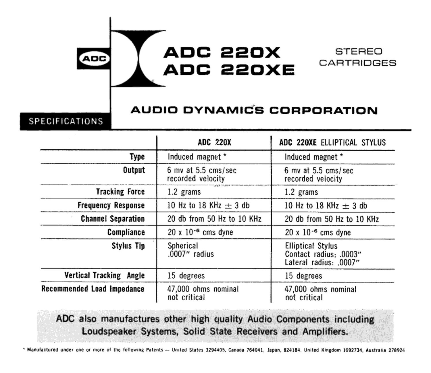
SPECIFICATIONS

ADO 220x
; ADO aaOXE

ADC 220x

STEREO
CARTRIDGES

AUDIO DYNAMICS CORPORATION

ADC 220XE ELLIPTICAL STYLUS

Type

Induced magnet *

Induced magnet *

Output

6 mv at 5.5 cms/sec
recorded velocity

Trackhli _. Force

1.2 grams

6 mv at 5.5 cms/sec
recorded velocity

1.2 grams

Frequency Response

10 Hzto 18 KHz : 3 db

10 Hz to 18 KHz : 3 db

Channel Separation

20 db from 50 Hz to 10 KHz

20 db from 50 Hz to 10 KHz

Compliance

20 x 10" cms dyne

20 x 10" cms dyne

Stylus Tip

Spherical
.0007" radius

Elliptical Stylus
Contact radius: .0003"
Lateral radius: .0007"

Vertical tracking Angle 15 degrees 15 degrees
Recommended Load Impedance 47,000 ohms nominal 47,000 ohms nominal
not critical not critical

ADC also-.manUfactures other high quality Audio Components including
Loudspeaker Systems. Solid State Receivers and Amplifiers.

' Manufactured under one or more ol the following Patents - United States 32944105. Canada 764041, Japan. 824184, United Kingdom 1092734, Australia 278924

Page 2

INSTALLATION

The cartridge is mounted in the tone arm
by means of the two 123-48 screws that are
supplied. Tone arm mounting centers of
either 1/2" or 7,316" are compatible with this
cartridge.

CAUTION: Do not solder leads to push on
terminals while they are mounted on the
cartridge terminal pins. The heat may cause
permanent damage to the cartridge.

GROUNDING

LEFT
CHANNEL
SIGNAL

RIGHT
CHANNEL
SIGNAL

LEFT
CHANNEL
GROUND

RIGHT
CHANNEL
GROUND

This ADC stereo cartridge is fully mu-metai shielded against stray hum fields. However. hum
can still be introduced in the system by incorrect grounding of the tone arm and turntable. The
tone arm body and turntable should be individually connected to the amplifier ground terminal

or chassis. This ground point should preferably be close to the pickup input ground.

PICKUP CABLES TO AMPLIFIER

The insulated shielded cables that connect the tone arm and amplifier should be no
longer than 5 feet, otherwise the capacitance of the cable will start to attenuate the high

frequency response of the cartridge.