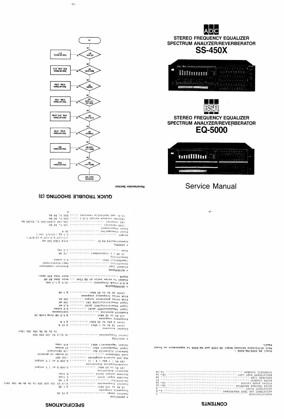
ADC SS 450X BSR EQ 5000 Service Manuals
This is the 13 pages manual for ADC SS 450X BSR EQ 5000 Service Manuals.
Read or download the pdf for free. If you want to contribute, please upload pdfs to audioservicemanuals.wetransfer.com.
Page: 1 / 13