Acurus p 10 owners manual

This is the 2 pages manual for acurus p 10 owners manual.
Read or download the pdf for free. If you want to contribute, please mail your pdfs to info@audioservicemanuals.com.

Page: 1 / 2
left right
acurus p 10 owners manual

Extracted text from acurus p 10 owners manual (Ocr-read)


Page 2

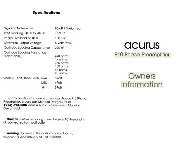
Acurus P10 Phono Preamplifier

Please read this manual. Upon completion you will
understand the set-up and operation of your P10 Phono
Preamplifier.

Connections

Before making any connections to your P10 Phono
Preamplifier, please be certain that the power cord is -'.
NOT plugged into an AC outlet. ,i

PHONO INPUT - Connect the right & left RCA phono
jacks of your turntable to the corresponding inputs on
the rear of the P10.
GROUND - Connect the ground wire from your turn-
table to the terminal marked Ground" on the rear of
the P10.
OUTPUT - Connect a high quality audio interconnect
from the output of the P10 to any high level input on 1!
your preamplifier (ie. Aux, Tuner, Tape, D/A etc).

User Adjustments

The Acurus P10 phono preamplifier utilizes All Discrete
Class A Circuitry. it also enables you to optimize the
characteristics of the circuit to match any specific
phono cartridge.

As shipped from the factory, the P10 is set for cart-
ridge loading of 47K ohms and medium gain. If you are
using a low output moving coil or high output moving
magnet cartridge, you may find it necessary to adjust
the Gain and Loading appropriately.

WARNING - Remove AC plug from wall outlet prior to
removing the cover. All adjustments MUST be made
with the power DISCONNECTED.

OK, now remove the cover . . . . the adjustments for
Gain or Loading must be done to both left & right
channels.

Gain Adjustment

On the right hand side of the circuit board are 2 blocks
marked GAlN (L & R). You will note the shorting bar
is located in the MED" position. To remove the shorting
bar, just pull upward and reposition on the two pins
corresponding to the appropriate gain setting. If you
find you need more volume then place the shorting bar
in the HI position. If you need less, then place the
shorting bar in the LOW position.

Loading Adjustment

Most moving magnet cartridges and some moving
coils are optimized for a 47K ohm load. Check with the
cartridge manufacturer for the proper loading for your
specific cartridge. Reposition the loading shorting bar
to the proper load position, as outlined in the gain
adjustment section above. When all adjustments are
completed, then replace top and reconnect the P10 in
your system,

Due to the P10s all discrete circuitry, it requires a
lengthy break-in period. Since the P10 is always on,
you will continually notice improvements during the first
240 hours.