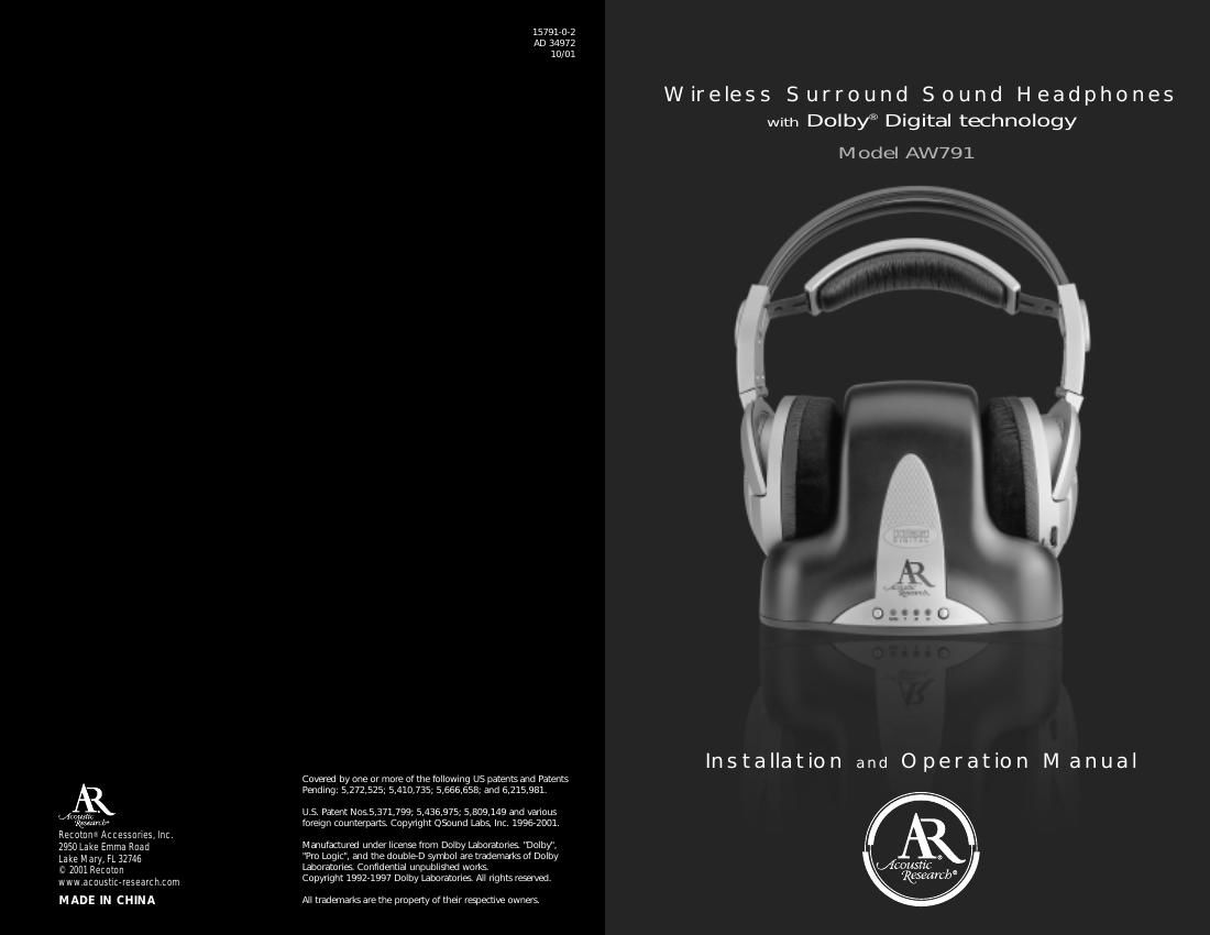
Acoustic research AW 791 Owners Manual

This is the 6 pages manual for acoustic research AW 791 Owners Manual.
Read or download the pdf for free. If you want to contribute, please mail your pdfs to info@audioservicemanuals.com.

Page: 1 / 6
left right
acoustic research AW 791 Owners Manual

Extracted text from acoustic research AW 791 Owners Manual (Ocr-read)


Page 2

Connecting the Headphone System i. Setup: Place the Transmitter in a location with enough clearance so that you can store the Headphones on the Transmitter. This is important, because the Transmitter charges the Rechargeable Batteries (P) inside the headphone\ s so they are always ready for use. See Charging the Batteries on page 5. You can use the Surround Sound Headphones with up to three different audio/video components. The three inputs on the transmitter -“ two digital and one analog -“ allow quick and easy connections for maximum versatility. ii. Connecting to Digital Components: a. Connecting Using the Supplied Toslink ®Digital Optical Cable: 1. Connect one end of theToslink ®Digital Optical Cable (Q) to the DIGITAL OPTICAL OUTPUT of your audio/video equipment. 2. Connect the other end of the Toslink ®Digital Optical Cable (Q) to the Toslink ®Digital Optical Connector (F2) on the transmitter marked Digital 2. b. Connecting Using a Digital Coaxial Cable: 1. Connect one end of theDigital Coaxial Cable (not included) to the DIGITAL COAXIAL OUTPUT of your audio/video equipment. 2. Connect the other end of the Digital Coaxial Cable to the RCA-type Digital Coaxial Connector (F1) on the transmitter marked Digital 1 . COMPONENT VIDEO RIGHT LE\bT VIDEO OPTICAL D-COAX OUTPUT DVD PLAYER RED GREE\f BLUE A B CA B CCHANNELCHANNEL DIGITAL 1DIGITAL 1 DIGITAL 2DIGITAL 2 ANALOG 3ANALOG 3 AC 7VAC 7V TRANSMITTER II COMPONENT VIDEO RIGHT LE\bT V DEO OPTICAL D COAX OUTPUT DVD PLAYER RED GREE\f BLUE A B CA B CCHANNELCHANNEL DIG TAL 1DIG TAL 1 D GITAL 2D GITAL 2 ANALOG 3ANALOG 3 AC 7VAC 7V TRANSMITTER - 3 - Location of Functions Transmitter Front View: A. Surround Sound ON/OFF Switch B. Surround Sound ON/OFF Light C. Input Indicator Lights 1. Digital Coaxial 2. Digital Optical 3. Analog D. Input Select Switch Transmitter Back View: E. AC Input Jack F. Input Connectors 1. RCA-type Digital Coaxial Connector 2. Toslink ®Digital Optical Connector 3. RCA-type Analog Left/Right Connectors G. Channel Select Switch Headphones: H. Battery Compartment I. Battery Compartment Cover J. Self-adjusting Headband K. Power Indicator Light L. Volume Control M. ON/OFF/Tuning Control N. Stereo Tuning Indicator Light Accessories: O. Transmitter AC Power Supply - 7V AC 1.4A P. Rechargeable Batteries 3 AAA Ni-MH Q. 3 ft. Toslink ®Digital Optical Cable SS 1 2 3 A B C1 C2 C3 D I A B CA B CCHANNELCHANNEL DIGITAL 1DIGITAL 1 DIGITAL 2DIGITAL 2 ANALOG 3ANALOG 3 AC 7VAC 7V EF1F2F3 G I J K H L N M --- +++ O Q P - 2 -