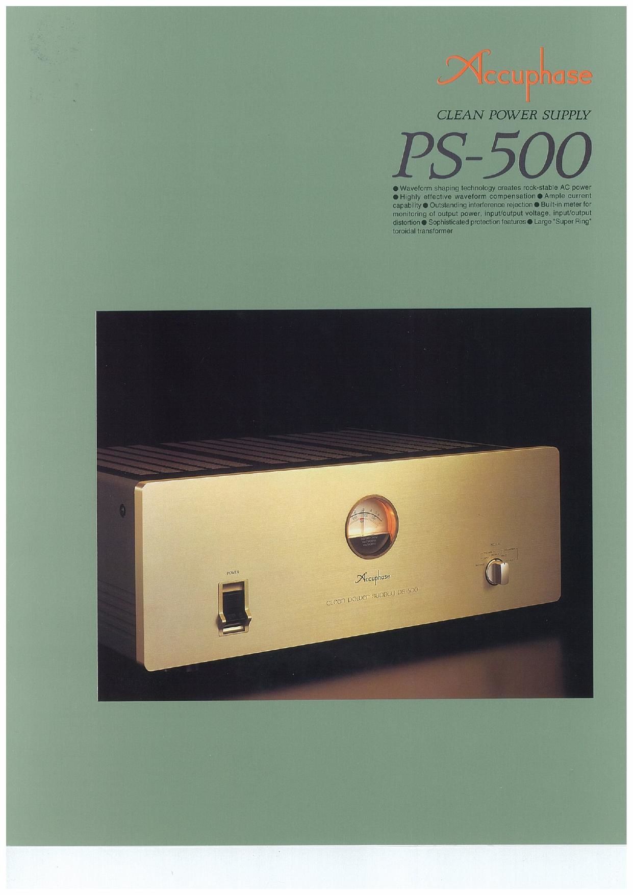
Accuphase PS 500 Brochure

This is the 4 pages manual for Accuphase PS 500 Brochure.
Read or download the pdf for free. If you want to contribute, please mail your pdfs to info@audioservicemanuals.com.

Page: 1 / 4
left right
Accuphase PS 500 Brochure

Extracted text from Accuphase PS 500 Brochure (Ocr-read)


Page 1

CLEAN POWER SUPPLY

5-500

0 Waveiorm shaping technology creates rockAslable AC power
.Highly etieciive waveiorm compensationoAmple curreni
capabiiiiy O Ouisianding inlerierence rejection 0 Buili-in mater ior
monitoring 0! output power. input/ourpul voliage. inpuVouipul
dislonion 0 Sophisticated proteciion isalures 0 Large 'Super Ring"
toroidal lransiormer

Page 2

The Clean Power Supply PS-SOO is a product that
breaks entirely new ground, Designed for audiophiles
and music lovers who will accept no compromises
when it comes to sound quality, the PS-SOO reflects
the extensive audio expertise accumulated by
Accuphase. It is a unique type of audio component
that goes far beyond conventional power supply
designs. Adding the PS-SOO to a high-grade music
reproduction system will result in sonic purity that is
nothing short of breathtaking.

The AC power lines in ordinary homes as well as in
office buildings. recording studios. and practically
everywhere else are supplying power to equipment
containing digital circuits and microprocessors which
includes not only computers but also many other kinds
of electrical appliances. High~frequency noise com-
ponents originating in such equipment can enter
audio components via the power supply and severely
affect sound quality by causing intermodulation noise
and distortion Only when such noise interference is
removed and totally clean power is supplied. audio
components become able to develop their full poten-
tial. Consequently. upgrading the quality of the AC
power source of an audio system is bound to result in
a drastic improvement in overall sonic performance.

In pursuit of the ideal. clean power. Accuphase has
developed a revolutionary new technique which con-
stantly monitors the input voltage waveform and adds
or subtracts exactly the required amount of compen-
sation to achieve a perfectly regular. sinusoidal wave»
form. The Fs-500 incorporates this technique. which
allows it to supply extremely stable and clean energy
to the components of an audio system. Using the
model of an ideal power supply waveform. a refer-
ence voltage is generated which serves as the yard-
stick for adding or subtracting just the right amount
of power to the input. The end result is output power
with perfectly clean waveform at all times. Since the
required compensation typically is only a fraction of
overall power. the F's-500 operates with high effi-
ciency and produces little heat. which allows it to be
deSigned as a fairly compact and lightweight unit, Of
course, the PS-SDO also has the ability to completely

block any high-frequency norse components. result»
ing in total absence of modulation noise. Since it conv
tains no oscillators or switching circuitry. the PS-SOO
itself does not act as a source of spurious high-fre-
quency noise.

Power Supply Waveform

The power generated by the power plant originally
is fed into the electrical grid with a clean sine wave»
form. However. when
power is withdrawn
from the local AC om-
let. the waveform al-
most invariably is
clipped, The reason
for this phenomenon
lies in the electrical
appliances used in the
household. Conven-
tional TV sets. per»
sonal computers.
audio components. as
well as many other ap«
pliances convert AC
input into a DC current
for powering the inter- Photo in; Voltage wmiomi at AC lino
rial circuits. This task l"°"°" 9" 3%)
is performed by a rec-
tifier consisting of a
diode and capacitor
arrangement. As
shown in photograph
(a). the rectifier load
current has a pulse
waveform. in the vicin-
ity of the voltage peak
of the sinus waveform.
a large current flows momentarily which causes a
voltage drop. or in other words a clipping of the volt-
age waveforrn. as shown in photograph (b). Aclipped
waveform with a high amount of distortion contains
many unwanted frequency components. or harmon-

mm la) Current wavzloim oi red-lied load

Photo (c) P5500 oulput wavelorm
idisronion approx. 0 2%)

Mater selector

Meter

Adder/subtracler

H @
fir

Line filter

it

Reamer


Waveform
comparator

Wavetarm compensatim
amplifier

Synchronized ref,
erence waveform
generator

Fig. 1 Operation Block Diagram of PS-500

Tap into a totally clean source of AC energy. Revolutionary waveform shap-
ing technology compares the AC input to an ideal sine waveform and pro-
vides highly precise compensation. High-frequency interference components
are reliably blocked, for further improved sonic purity. High capacity of
500 VA accommodates a wide range of audio equipment. Monitoring of out-
put power, input/output voltage, and input/output distortion is also possible.

ics. When entering the audio circuitry of an amplifier
through the power supply. such harmonic compo-
nents can interfere with the audio signal and cause
lntermodulatlon distortion which has a highly detri-
mental effect on sound quality.

When passing through the PS-500. the deformed
waveform is restored to its original sine wave pat-
tern. as shown in photograph (c). This clean power.
when supplied to an audio component. causes a
drastic improvement in sonic purity.

AC Voltage Stabilizer Based on Waveform Shap-
lng Technology

The PS-500 accepts AC power on the input side. pro-
cesses it using internal control circuitry. and supplies
it as clean AC power on the output side. Most of the
AC energy from the input is carried over to the out-
put. The loss introduced by the PS-500 is very small.
since it consists only of the power required for wave-
form compensation. Compared to conventional AC
voltage stabilizers. efficiency is much higher and ex-
cess thermal energy is low. allowing the unit to be
made relatively small and lightweight. Since the power
supply frequency is synchronized to the input. an in-
ternal oscillator is not required. Therefore, the unit
itself does not generate any high-frequency noise.

Figure 1 shows the circuit diagram of the unit. The
signal from the i
secondary wind- fiflw
ing Si of the trans-
former is routed a» so
through the add-
ing/subtracting
circuit and ap-
pears at the out-
put as output ---W
voltage (So). The wwmmlwi
52 signal from the Output power/Input power (efllcllncy)
. characllrlltlc:

transformer IS

supplied to the WWW . . .
reference wave» -
form generating
circuit where it is '.

turned into the j

rm v-aso

' inviii'mm

Lend man

ii.
i
i::
i

. , l

high-precision ,, 1 .i

sine waveform (ei) I . . . . l

. l . i
synchronized to u .0. m w,

m
Oulnm power lWl
Outpul power/THD characterlstics

Fig. 2 P9500 Load Characteristics

the input fre-
quency. This sine
wave signal is then
routed to the waveform comparator to be used as
reference signal. By comparing the output voltage (ea)
to this reference sine waveform (er). the differential
component is detected. Based on this information.
the adding/subtracting circuit can provide exactly the
required amount of compensation for turning the out-
put into a high-precision sine waveform.

Superior Waveform Compensating Power
Generally speaking. if the input voltage is for example
1 10V/220V. 10 volts must be added to bring it to 120W
230V, as shown in Figure 3 (a). Conversely, if the in-
put is 130V/240V. 10 volts must be subtracted to yield
120V/230V. (Actually. the peak value of 10 V. namely
14.1 V is subtracted.)

By comparing a precise sine wave synchronized to

Page 3

the input frequency With the output voltage, a com-
pensation waveform is created which is then imposed
on the output voltage. Consequently. for an input volt-
age range of 108-132V/200-253V AC and a constant
load of 500 W, the output voltage is kept constant at
120V/230V ( i 2%), with a maximum distortion ratio
of 0.3%. These values demonstrate the outstand-
ing waveform compensation ability of the Fs-500.

iAc Mun .. Wynn

/
tiu aw

in) Ii iownrtttan mum v Ac. positive (b) it highni than iznim vac. tugs
campsnsaiian is ntldafl live campensalinn is «and

Fig 3 Waveform Shaping Principle of PS-500

Excellent Current Capability

The power amplifier which performs waveform com-
pensation is configured as a pure complementary
symmetrical circuit using current feedback for unsur-
passed operation stability. The output stage uses tran-
sistors rated for a maximum current of 10 amperes.
These devtces are connected in a ill-parallel comples
mentary push-pull arrangement which boasts a rated
output current oi4.2A/2.2A and an instantaneous peak
current rating of GOA/30A. This kind of current cape»
bility is an order of magnitude better than that of con-
ventional power supplies.

Highly Effective interference Rejection

The input side of
the PS-500 also
contains a line filr
ter for removing
highsfrequehcy
noise components
t h at m a y b e
present in the
power line. The pri-
mary and second-
ary windings of the
power transformer
are kept totally
separate, and the
fully shielded de
sign shuts out any
externally induced
noise.

Since the PS-SOO
uses the AC feed-
back principle.
output imped-

ini rreqwnsy spectrum of Pssm umput (photo c)

Fig. 4 Power Supply Frequency Spectrum

Motel scnlo ivoiingn indica-
tion) is uiiiemni in in v and
m v Ac vnisiuns.

Assembly with vinveioim ccmpensaliun :tm
'ADV for a nlsuhlrnctmm output stage with 10-53.
nllel pusinpuii m mittor devices mounted In llrgc hunt
sink. cumpnralnr luv retort-rice wavstorm and output waveform.
deviation noiuioi. etc.

ance is extremely low. This prevents any possibility
of mutual interference between components con-
nected to the outputs of the PS-SOO.

Figure 4 shows the frequency spectrum of the power
supply line and the PSVSOO output, It clearly demon-
strates that unwanted high-frequency components
Within the audible range are effectively suppressed
by the Fs-500.

Built-in Meter Allows Monitoring of Output Power,
Input/Output Voltage, Input/Output Distortion
The meter of the Fs-500 lets the user see at a glance
how much power the connected equipment is con~
suming at any given time. This is especially helpful for
components such .

as integrated ampl

liers or power ampl

fiers whose power

consumption differs

considerably de-

pending on the vol-

ume setting and . . .
_ Assembly with input voltage/dismrhon
actual music signal. monitoring nircuilfy