Accuphase P 350 Brochure

This is the 4 pages manual for Accuphase P 350 Brochure.
Read or download the pdf for free. If you want to contribute, please mail your pdfs to info@audioservicemanuals.com.

Page: 1 / 4
left right
Accuphase P 350 Brochure

Extracted text from Accuphase P 350 Brochure (Ocr-read)


Page 1

MECUPLGSG

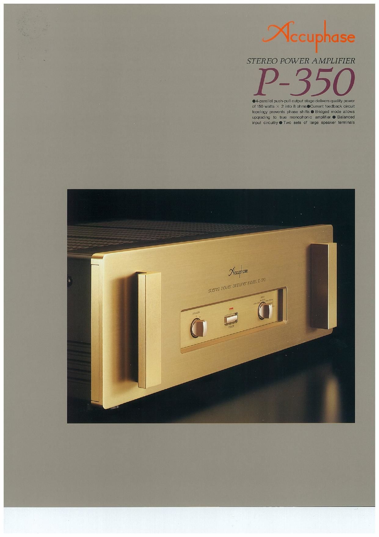
STEREO POWER AMPLIFIER

P-350

.4-parallel push-pull output stage delivers quality power
0! I50 watts )1 2 inlo B othOCurvent fleedback circuit
topology prevents phase shifts O Bridged mode allows
upqrading to true monophonic amplifier 0 Balanced
input circuitryOTwo sets 0! large speaker termmals

Page 2

The fundamental requirements of a power
amplifier can be summarized into two points.
The amplifier must possess the energy
resources to deliver a large current to its con-
nected loudspeaker load, and at the same
time, it must be capable of reproducing the
ambience and true depth of the sound stage
with absolute fidelity, even at very low signal
levels. In addition to these two basic condi-
tions, the output stage of the amplifier must be
designed in such a way that it will not be
affected by the considerable fluctuations in
loudspeaker impedance, which occur depend-
ing on the frequency of the signal.

To fulfill these demands, the P-SSO employs
multi-emitter type power transistors specially
developed for high-power audio applications,
These sophisticated devices have excellent
frequency response, and oustanding forward-
current transfer ratio linearity as well as switch-
ing characteristics, With these transistors
arranged in a 4-parallel configuration, the
P-350 delivers 150 watts of quality power into 8
ohms per channel. By using bridged mode, the
P-350 can be turned into a monaural power
amplifier with an output of 420 watts into 8
ohms, for even more rich, musical presence
and impressive dynamism

Another design highlight of the P-SSO is the
"current negative feedback" principle. As
opposed to conventional voltage NFB designs,
there is virtually no phase shift in the upper
frequency range, and frequency response does
not change as gain is altered. This circuit
topology guarantees ideal amplification char-
acteristics, combining operation stability with
excellent frequency response. Phase compen-
sation can be kept at an absolute minimum,
since only moderate amounts of NFB are
required, This assures outstanding transient
response with pulse signals, and the advan-
tages are clearly audible as to superb sonic
realism and extraordinary detail resolution.

The basic source of energy for an amplifier is

Current feedback circuit topology assures
passed sonic realism and extraordinary detail resolu-
tion. 4-parallel push-pull output stage with multi-
emitter power transistors delivers 150 watts/ channel
of quality power into 8 ohms.

Bridged mode allows upgrade to a monophonic power
amplifier with 420 watts into 8 ohms.

of course the power transformer and the filter-
ing capacitors, The P-SSO features a large 700
VA power transformer and capacitors with
ample filtering capacity. This huge power sup-
ply block with ample surplus energy greatly
contributes to the realization of powerful and
dynamic bass reproduction. And to maintain
absolute sonic purity, important parts such as
input terminals and printed circuit board traces
are gold-plated.

Externally, the simple and refined design
reflects the utterly natural and pure sound of
this fine amplifier.

Output stage with 4-parallel push-pull configu-
ration delivers quality power of 210 watts into
4 ohms or 150 watts into 8 ohms per channel
The output stage uses multivemitter type power
transistors specially developed for audio appli»
cations and rated for a Power Input to Collector
of 100 watts and collector current of 10 ampere.

These devices offer

extraordinarily wide /

and flat frequency ,

response, and their e
forward-current

transfer ratio linearity
as well as their swit-
ching characteristics
are excellent. By
arranging these transistors in a 4-parallel push-
pull configuration, the P-350 achieves ample
power output capabilities, providing 210 watts
into 4 ohms and 150 watts into 8 ohms per
channel. Figure 1 shows the output circuit
configuration of the P-350.

%.
ii \ Mulii-emxllur

1ch now trunsmroi

Current feedback circuit topology prevents
phase shifts

When the gain of an amplifying circuit
increases, frequency response, i.e. the ban-
dwidth that can be handled by the amplifier.
becomes more nanow. To counter this effect. a
commonly employed technique called negative
feedback (NFB) routes part of the output signal

cv

ilNPUT 0- 0

{saw |- .5,

+82

O OUTPUT

thFUT 0-..-

Flg.1 Circuit Diagram ol the Amplililr Unit (One Channel)

*Bz

unsur-

back to the input. lf phase shift is disregarded,
a circuit designed to have high open-loop-gain
can apply a
high amount of
NFB, resulting
in the wide
fre q u e n c y
response of a
closed-loop
circuit, as
shown in Fig-
ure 2.

Conventional amplifiers employ voltage NFB,
whereby the output voltage is used for the
feedback loop. In the P-350, however, the
signal current rather than the voltage is used
for feedback. Figure 3 shows the operating
principle of this circuit. At the sensing point

ma)

Gain a

Frequency _. rm

Fig.2 Fwy "spam with vniiagu rmm
(Response change: when gain is varied)

Trannmmanua new"

1
7 35>? CflSEi amplifier nmnllilnr
Buffer . .. "V 4
V convene! Output
,_

t Input
Bun" _______ Current NFB _._.*..
network

Fig.8 Princlplo of current feedback lmpllflar

of the feedback loop, the impedance is kept
low and current detection is performed. A
trans-impedance amplifier then converts the
current into a voltage to be used as the feed-
back signal. Since the impedance at the cur-
rent feedback point (current adder in Fig. 3) is
very low, there is almost no phase shift. Phase
compensation therefore can be kept at a
minimum. resulting in excellent transient
response and superb sonic transparency.

With this circuit, there is virtually no change in
fre q u e n c y , .
response when
gain is altered.
Figure 4 shows
fr e o u e n c y
response for
different gain

ruair'

Gain 4_

settings of the Evenuency ..._ nu)
current feed- FIgA Frequency mm wllh current mam
back amplifier {Response do" not criange when gain I: varied]

The graphs demonstrate that response remains
uniform over a wide range.

Bridged operation mode creates a true mono-
phonic amplitier with 420 watts into 8 ohms

Bridged mode means that the two channels of
an amplifier are driven with the same signal
voltage but with opposite phase, and their
output is combined. The P-350 provides a
switch arrangement for bridged operation,
which turns the unit into a high-grade monaural
amplifier capable of delivering a full 420 watts
into 8 ohms. Simply by adding another P-350 to
form a stereo amplifier pair, a further improve-
ment in sonic performance can be realized,