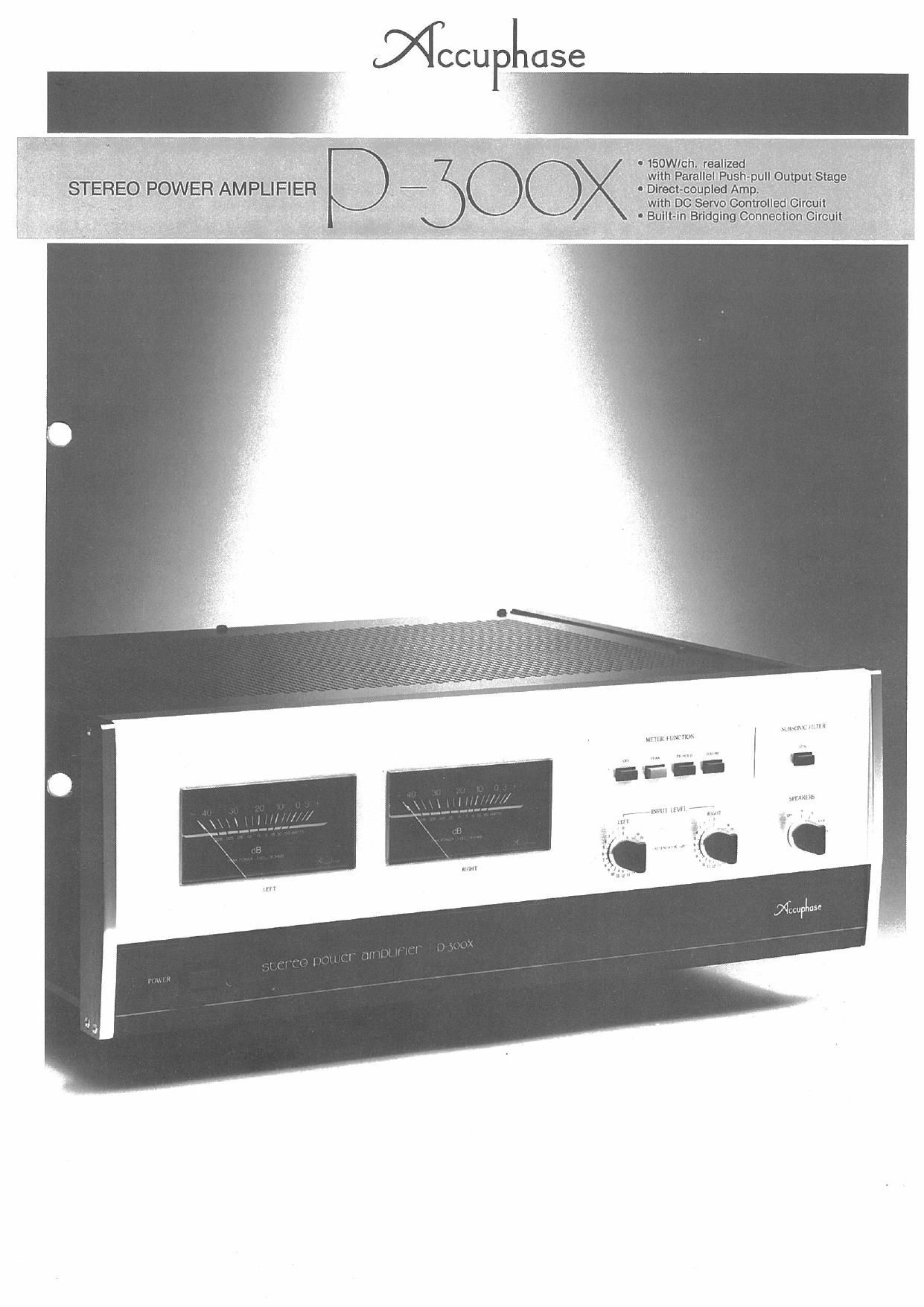
Accuphase P 300 X Brochure

This is the 4 pages manual for Accuphase P 300 X Brochure.
Read or download the pdf for free. If you want to contribute, please mail your pdfs to info@audioservicemanuals.com.

Page: 1 / 4
left right
Accuphase P 300 X Brochure

Extracted text from Accuphase P 300 X Brochure (Ocr-read)


Page 1

- 150WI_ch. realized , _ '
wllh Parallel Push-pull OutpulIStage ,
, - - DIrect-qoupled Amp. _
' wlth DC Servo Controlled Clrcult 1
- BulIl-in Bridglng Gonnectlon Cltcult

«V

' STEREO POWER AMPLIFIER

Page 2

Employing the latest bipolar transistors which have superior high
frequency characteristics in its parallel push-pull output stages, the
Accuphase P-300X is a stereo power amplifier which can deliver ample
power of 150chh into 8 ohms.

Complementary-symmetry. push-pull circuitry. a consistent practice
with Accuphase since the widely successful P-300. is used in all stages.
but the P-SOOX also introduces a newly developed "Cascode Bootstrap
Differential Amplifier at its input. which has further improved performance
characteristics.

In its power supply which is the most vital section for any power
amplifier, the P-BOOX employs separated, independent windings ol the
power transformer secondary for each channel

The PSOOX incorporates other significant functions. such as a builtrin
Bridging Circuit which, by simple switch action. can transform the P-300X
into a powerful 400W monophonic power amplifier that can supply ample
power to a dynamic sub woofer system. or effectively contributes to
upgrading the system With more power by adding another P-300X.

it also has Input/Output connectors hidden behind the front Sub Panel
for convenience in testing various audio equipment.

In designing the P-SOOX, Accuphase attached the greatest im-
portance to give it the capability to deliver a deeper. more vigorous
description of music which contains greater detail and background
atmosphere.

fl PARALLEL PUSH-PULL OUTPUT STAGE
DRIVEN BY MOS FET DRIVER STAGE

The amplifier circuit diagram below shows that MOS FETs (Metal-
Oxide Semiconductor Field Ettect Transistors) are used in the driver stage
and bipolar transistors. which are the latest wide frequency types. are
used in the output stage. The use of MOS FETs in the primary stage stabi-
lizes the bias voltage of the output stage. and eliminates the need for
emitter stabilizing resistors. This has prevented swrtching distortion. since
the bias of the output transistor is never out off even at peak output levels.

Another advantage of using MOS FETs in the driver stage is that
because of their very high input impedance, the operation of the pre-drive
stage is greatly stabilized. which also contributes to higher overall
performance.

2 CASCODE PUSH-PULL PRE-DRIVER GREATLY
' IMPROVES HIGH FREQUENCY PERFORMANCE

The ore-drive stage which must supply large voltages and high current
to the driver stage is most vital as it governs the performance of the entire
amplitier. Wide band amplification is achieved in this stage of the P300X
by using transistors in cascode connection.

013 to 016 of the diagram shows the cascode connections of the pre-
drive stage. Ample high gain is achieved with common-emitter connection
of 013014. and high amplitude voltage with common-base connected
transistors 015016 which have resulted in superior high frequency
characteristics void of Miller effects. The cascode connection of tran-
sistors in which one pair handles large currents. and the other high ampli-
tude voltages, has completely solved the characteristics shortcomings
of pre-driver stages.

01

at

m
02 or

ru 5; R,

Diagram of Cascode Bootstrap connection Input stage
and Parallel Push~pu|l Output stage

Q CASCODE BOOTSTRAP DIFFERENTIAL
PUSH-PULL INPUT STAGE

The differential ampliiier circuitry in the input section consists of 01
to 011. its input stage employs P-Channel and N-Channel FETs in push-
pull arrangement which is cascode connected to the next stage constst»
ing of 03 04. The source electrode of Qi is connected to the base elec»
trode of 04 through R7. and the source electrode of 02 is connected to
the base of 04 through R6 in a bootstrap pattern.

Very stable wideband amplification was achieved by employing this
cascode bootstrap circuitry. which not only contributed to high gain and
improved high frequency characteristics. but also practically eliminated
any increase in distortion when input impedance is raised (as when
volume control is adjusted).

Test data on actual distortion characteristics of the P-SOOX appear on
the next page. It shows that intermodulation distortion and transtent
intermodulation distortion are completely absent. and confirms that its
overall distortion characteristics are very close to the ideal, -

O

(J,

A}? DC SERVO CONTROL CIRCUITRY

Input capacitors were eliminated by employing FETs at the input as
can be seen from the circuit diagram. This would mean that DC com-
ponents in the input signal would also be amplified. so that any DC leakage
from an associated preamplifier would pose the risk of damaging the
speakers.

Such direct currents must be blocked in order to protect the speakers.
The P-300X has a DC Servo Control circuitry which not only effectively
blocks such direct current, but it also neutralizes any DC drift that may
occur in the power amplifier circuitry itself, The ID in the circuit diagram
shows this DC Servo Control circuit.

HIGH PERFORMANCE POWER SUPPLY
FEATURES SEPARATE POWER SOURCES
FOR EACH CHANNEL

The importance of a power amplifiers power supply which must
deliver rapidly changing energy to the speakers increases in direct
relation to the quality of high grade amplifiers. The power supply must not
only have sufficient power supplying capacity. but it must not cause
interchannel interference. .

The P-SOOX has a high performance power supply which compl
eliminates such possibilities by using separated secondary winding 0 e
power transformer which lead to independent rectifiers and filter capac-
itors that make up a separate. exclusive power source for each channel.

Power tram:

Power Amp. Unit (one channel)