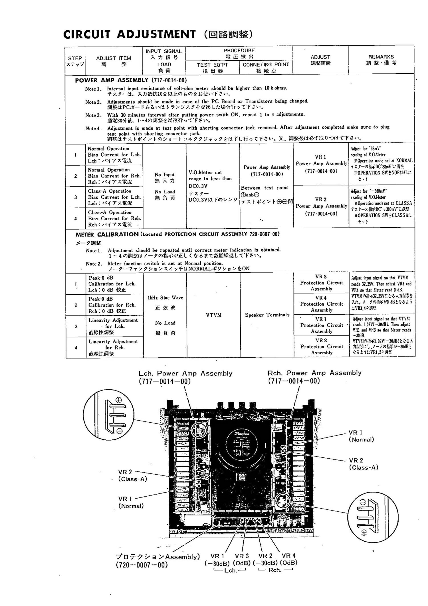
Accuphase P 266 Schematic

This is the 2 pages manual for Accuphase P 266 Schematic.
Read or download the pdf for free. If you want to contribute, please mail your pdfs to info@audioservicemanuals.com.

Page: 1 / 2
left right
Accuphase P 266 Schematic

Extracted text from Accuphase P 266 Schematic (Ocr-read)


Page 1

CIRCUIT ADJUSTMENT (@Efiéfiifé)

7' 7~.7-l:l. 7x71337009 LII/3 {a fiéfilfiwléw:

Note 2. Adjustments should be made in case of the PC Board or Transistors being changed.
flfifliPCrK- F '55 Ii Is 5 / "x Z 9 2 iii? L EIKIfifi'o ET-E" Ls

Note3. With 30 minutes interval after putting power swith 0N. repeat 1 to 4 adjustments.
inflame. 1~4md§lf5-£ R'i'héiTo "CI"? I.

Noted.

test point with shorting connector jack.

INPUT SIGNAL PROCEDURE
STEP ADJUST ITEM A 73 1% s; a? E I; a: ADJUST REMARKS
1777 is] g LOAD TEST EQ'PT CONNETING POINT ifilfiifi _ EH % ffi %
a Ts? Is It as IE ff: as i
POWER AMP ASSEMBLY (7I7-00I4-00)
Note 1. Internal input resistance of volt-ohm meter should be higher than 10kohms.

Adjustment is made at test point with shorting connector jack removed. After adjustment completed make sure to plug

iJ-wlfiélii'x htfivf / lmf/a- l 33779r -7 fléli'iLfioCTébm 1. fifiifili-flflfl) OUT-F3.

Normal Operation
I Bias Current for Lch.
Leh I '4 Tlfifilf.

Normal Operation

VR 1
Power Amp Assembly

(711-0014410)

Power Amp Assembly
V.0.I\leter set

Adjust Ior 'XSITIII"
reading ol 0.11:!"
E0peralion mode set at XORIIAL
717-lfidWC38mVifiifi1
fiOPERIITlOX SII'E'XORIIAL:

+7}

2 Bios Current for Rch. N0 Input (717-0014-00)
Rch Z .4 7Xiiii g 7\ 7 range to less than
DCO.3V _ .
0355.11 Operation No Load Txy- Betneen test pom:
3 Bias Current for LEI]. 5 1:1 fij 6%an

DC0.3VL1F7>V 9:; VR2
Power Amp Assembly

(71770014-00)

Lch:r<477~$afi ixld-Mxleefifl

CIEISSA Operation
4 Bias Current for Rch.
RclI Z 1"4 716.5%

Adjust Int "30ml"

reading of \.0,I\Ietzr
§0pmtinn node set at CLASSA

'7' 7t 7-fllffiiDC' 73flDmV'IZ £93}
EOPERATION SWECLASS. 1:

$7,;

METER CALIBRATION (Located PROTECTION CIRCUIT ASSEMBLY 720-0007-00)

2 - 9 EEE
Notel. Adjustment should be repeated until correct meter indication is obtained.
1 ~ 4 0311.54. X -77)1§d§f)JEL < (I 5 3. T'fllflfliEL CTE.
Note 2. Meter function switch is set at Normal position.

l-9-77J7Ja 75M 77I3NORMALFK799xEON

Adjust input signal so that VTVII
reads 32.2w. Then adjust VRZ and
VIII so that Meter rud 0 dB.
\"I'\'.\mifi'.1:32.25\"l:"; 5 ME I?!
AIL. 1-77. am dBk-Z'Eal'i
1:VR3,4-3£¥.

Peak-I] dB VR3

l Calibration for Lch. Protection Circuit

' Lch 2 0 dB QUE Assembly
Peak-0 dB 1m; Sine Wave VR4

2 Calibration for Rch. . . Protection Circuit

2; e
RCII : 0 dB mi 115 i '& Assembly
VTVM Speaker Terminals »

Linearity Adjustment N Load VR 1

3 - for Lch. 0 Protection Circuit -
fifillilfiffi 212 fi 'f'Jf Assembly
Linearity Adjustment VRZ

4 for Rch. Protection Circuit
Ififififilfllfi Assembly

Adiusl input signal so [hat I'TVII

' reads 1.02Vi-30dBi. Then adjust

VIII and VR3 so that Meier reads
-3Ild8.

VTVIIQIfiiIEI .02\"3 30dBE 2 57.» I1
11 In}: L _ I - ifllfiIzW-Slldfl':
15 l 'i.1\Rl.2i'iIif.§

Lch. Power Amp Assembly
(717-9014-09) (717-0014-00) -

\ l/
/


VR 2
(ClaSS-A)

VR I
7 (Normal)

/ .
TE! :7"? 7 a f/Assernbly) VR 1
(720*0007-00)

VR 3
(-30dB) (OdB) (-30dB) (OdB)

VR2 VR4

L- Lch.5-' - Rch. -

Rch. Power Amp Assembly

VR I
(Normal)

VR 2
(Class-A)