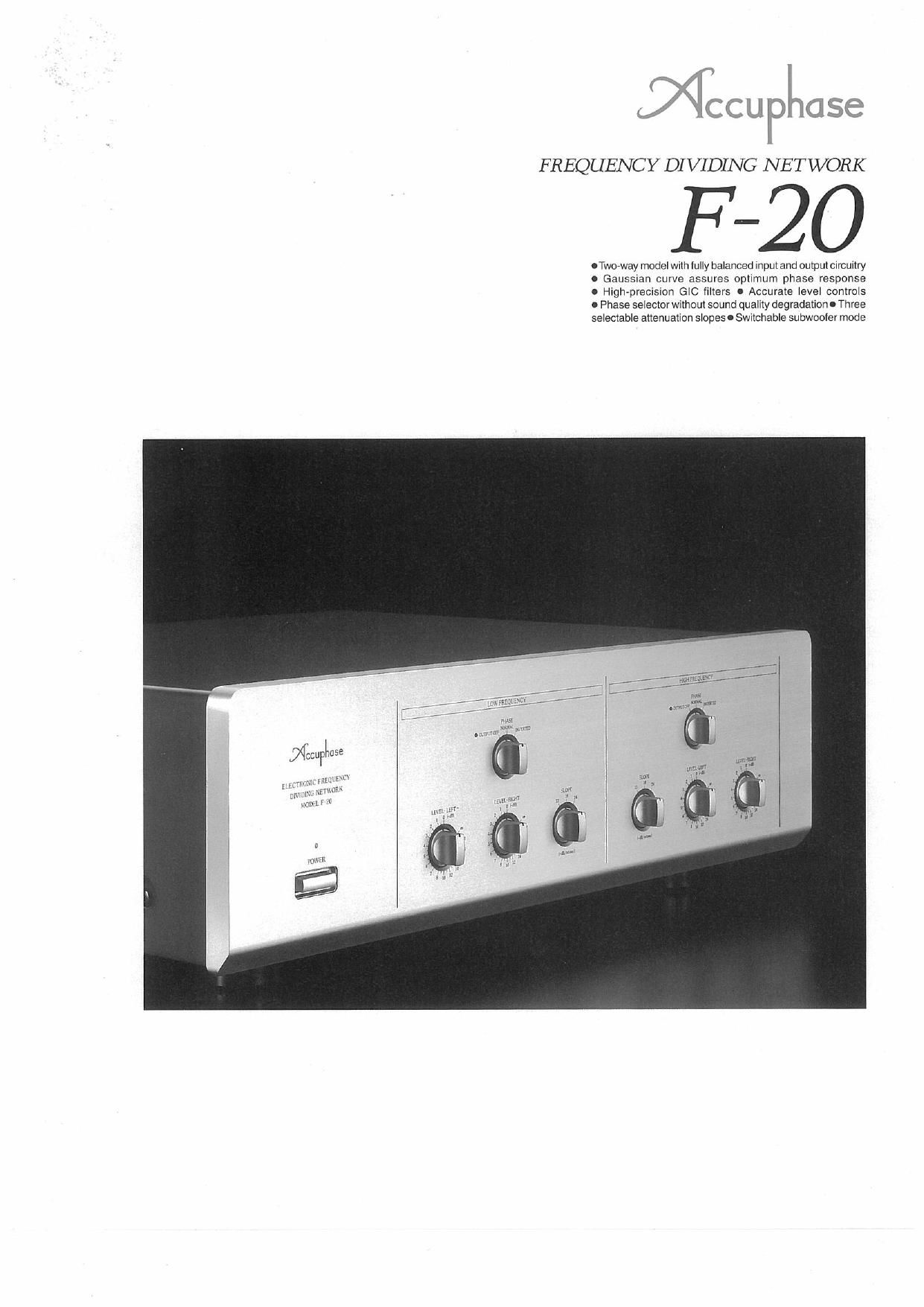
Accuphase F 20 Brochure

This is the 4 pages manual for Accuphase F 20 Brochure.
Read or download the pdf for free. If you want to contribute, please mail your pdfs to info@audioservicemanuals.com.

Page: 1 / 4
left right
Accuphase F 20 Brochure

Extracted text from Accuphase F 20 Brochure (Ocr-read)


Page 1

FREQUENCY DIVIDING NETWORK

F -20

ITwo-way mode! wnhlully balanced inputand ompmcircuwtry
o Gauss>an curve assures optimum phase response
0 High-precision GIC filters 0 Accurate leve controls
0 Phase se4eclorwx|hout sound quality degradation-Three
selec1able anenualion shapes I Swnchable subwooler mode

u/
rm
.... W,

.1

um I n

Page 2

The F-20 is designed to serve as the heart of
a high-quality multi-amplification system. It is
a two-way frequency dividing network
incorporating sophisticated technology
developed for the highly renowned
multichannel model F-25. Multi-amplification
systems-where each speaker unit has its
own dedicated power amplifier-are the
pinnacle on the road to audio perfection.The
increased complexity of such a system is
offset by the dramatic increase in sonic
definition and musical accuracy. Another
advantage for the serious audiophile is the
fact that it is possible to pursue one's own
sonic ideals without compromise

The F-20 reflects the long experience of Accu-
phase with balanced signal transmission.
Another important feature are the GIC filters
built with strictly selected high-quality devices.
The filters are designed with a Gaussian curve
which assures excellent phase and impulse
response characteristics, ideally suited to the
properties of the musical signal. Three atte-
nuation slope settings (-12 dB/octave. -1 8 dB/
octave, ~24 dB/cctave) can be chosen inde-
pendently for the LOW and HIGH frequency
range.The GIC (Generalized lmmittance Con-
verter) principle used for the filter circuits can
simulate the action of an LC filter without the
adverse effects of inductance. Circuit constants
can be precisely selected, to achieve highly
accurate crossoverfrequency and attenuation
slope settings. The music signal in the pass-
band is not routed through an amplifierwhich
is highly desirable in terms of signal purity

The crossover frequency is determined by
filter boards which are available as options

and are inserted in rear-panel slots. This
allows the shortest possible connection to the
filter amplifier, to prevent signal degradation.
A wide range of boards for different
frequencies are available. The balanced
principle used for the input and output stages
assures high S/N ratio. All aspects of this
product reflect the technological expertise
and multi-amplification know-how accumulat-
ed by Accuphase over many years.The F-ZO
is easy to use and provides an effortless entry
into a new dimension of audio enjoyment.

Dedicated Two-Way Dividing Model With
Totally Balanced Input and Output Stages
Balanced signal transmission employs two
identical signals with opposite phase. which
makes it possible to completely cancel out
any high-frequency noise or other
interference components that may enter the
signal path via the wiring or the power supply.
This is especially important in multi-
amplification systems where longer cable
runs and more connections are required.
As shown in Figure 1, the F-20 is a dedicated
two-way frequency divider with balanced input
and output stages. Balanced lines are
especially desirable for high-efficiency horn-
loaded drivers. which benefit notably from a
noise~free, highly pure signal. A rear-panel
switch allows the use of unbalanced lines as
well, if desired,

Gaussian Curve Filter Characteristics
Assure Superior Phase Response

The F-20 adopts filters with Gaussian curve
characteristics. which are mostly found in
high-precision measurement instruments and

va

New;
use an

tm mm, Etzwzur


cmwxn " mm
(@1 mm {a

slam


imam: my

anmcm mm

W Mum mmuzncv BoARntoerwl/FUER AWIFIER

. use
@T"
+

New
cumin.

5.». LEW CHANNEt

Fig.1 F-Zo BIocfoDiagram

Scale the Pinnacle of Sound With a Multi-Amplification System.
Two-Way Frequency Dividing Network Offers Fully Balanced Input
and Output Stages. High-Precision GIC Filters and Gaussian Curve
Assure Great Sound and Excellent Phase Characteristics. Choice of
Three Attenuation Slopes in Each Frequency Band.

FFT analyzers. Compared to conventional
Butterworth type filters, they provide superb
impulse and waveform fidelity.

High-Precision GIC Filter Circuits

The filter circuits employ the GIC (Generalized
lmmittance Converter) principle.The low-pass
filter is shown in Figure 2 and the high-pass
filter in Figure 3. Whereas conventional filters
require inductance (L) and capacitance (C),
the GIC type filter achieves the same effect
using only capacitance (C) and resistance (Fl).

Fig.2 GIC Type Low-Puss Filter
(-1adB/octavei

mm ourPur

HF

Fig.3 Gic Type ngh-Pass Filter
(-18dB/octave)

As opposed to conventional feedback-type
filters, the GIC filter does not require the signal
in the passband to be routed through an
amplifier which is highly desirable in terms of
signal purity, Circuit constants can be
precisely selected, thereby achieving highly
accurate crossoverfrequency and attenuation
slope settings.

Three Selectable Attenuation Slopes

A front-panel selector allows the user to
choose between three different slope settings:
-12 dB/octave, -1 8 dB/octave, and -24 dB/
octave.The higherthe figure, the steeperthe
cutoff curve, i.e. the more thoroughly the
suppression of other fre- stave
quencies. Separate select- '1 m 7
ors are provided for the

HIGH and LOW channels,

allowing individual adjust-

ment. tan/.5.)