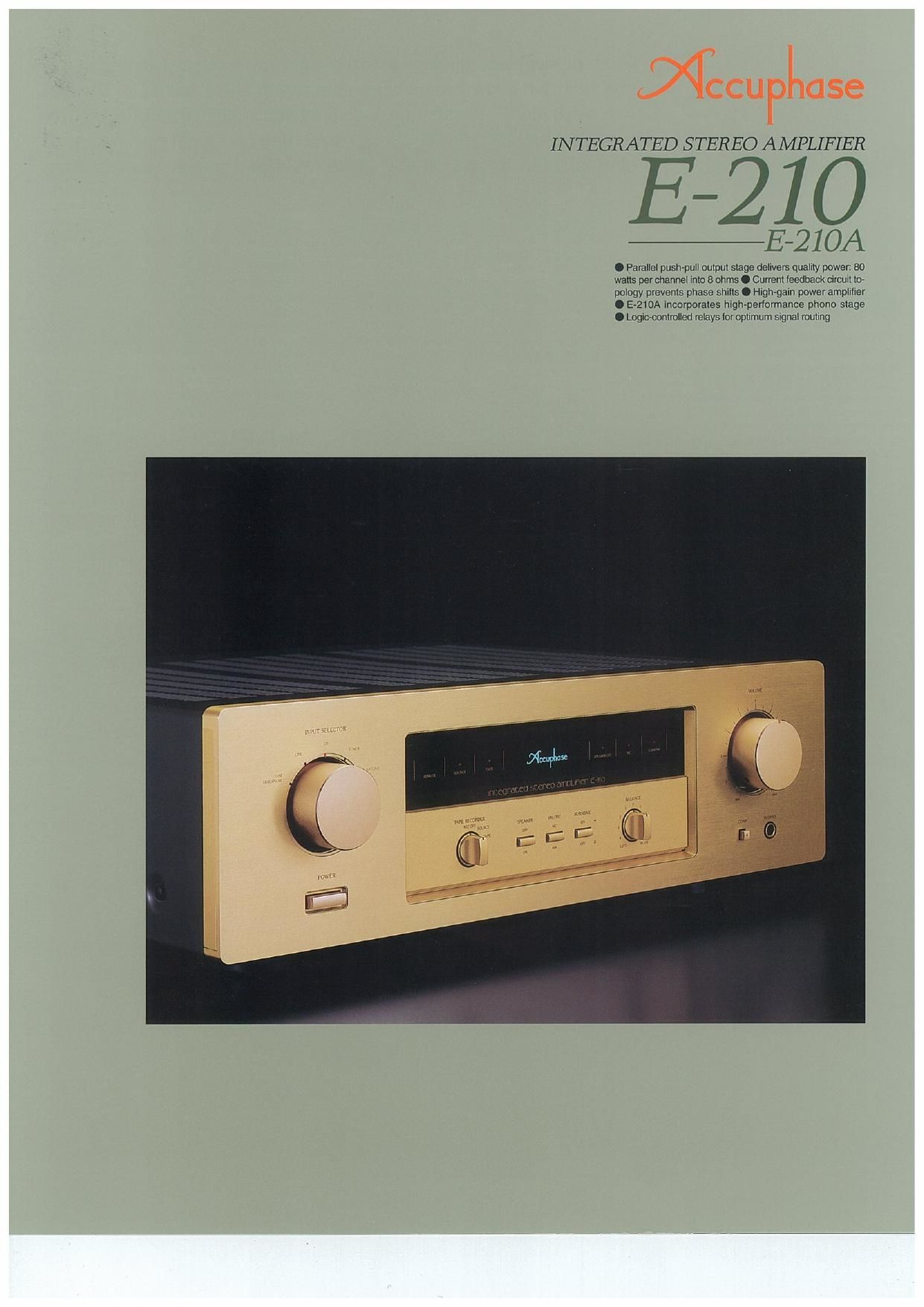
Accuphase E 210 Brochure

This is the 4 pages manual for Accuphase E 210 Brochure.
Read or download the pdf for free. If you want to contribute, please mail your pdfs to info@audioservicemanuals.com.

Page: 1 / 4
left right
Accuphase E 210 Brochure

Extracted text from Accuphase E 210 Brochure (Ocr-read)


Page 1

INTEGRATED STEREO AMPLIFIER

E-210

#E- 210A

0 Parallel pusn»pul| oulpul slage delivers quallly power: 80
walls per channel lnlo 8 ohms O Currenl leedback circuit lav
pology prevenls phase shifts O ngh-gain power amplilier
O E-210A incorporates high~perlormance phone slage
O Loglcmnlmlled relays (or optimum signal roullng

Page 2

The E-210/E-210A is an integrated amplifier based
on superior Accuphase technology developed for
our celebrated separate components. While sur»
prisingly affordable, the E-210/E-210A delivers
performance that far surpasses the realm of con-
ventional integrated amplifiers. The E»210 is con-
figured as a line-level amplifier, whereas the
E~210A integrates a phono amplifier stage which
will be welcomed by audiophiles with a treasured
collection of analog records.

The most important circuit feature of the E~210/E-
210AiS the high-gain power amplifier principle (Fig-
ure 1) which feeds the line-level signal directly to
the power stage, This keeps the signal path desir-
ably simple, while totally eliminating the possibil-
ity of mutual interference between the low-level
signal switching sections and the power amplifi-
cation circuitry. The audible benefit is a clear im-
provement in sonic purity. Another significant
advantage is the current feedback topology de-
veloped by Accuphase. It virtually eliminates phase
shifts in the upper frequency range and assures
uniform frequency response which does not
change with gain. In other words. it combines
total operation stability with excellent frequency
response. Thanks to this principle. phase
compensation can be kept at a minimum, and high
amounts of negative feedback with their asso-
ciated disadvantages are no longer required. This
assures excellent transient response, with superb
sonic transparency and detail. Music reproduced
with the E~210/E>210A sounds almost uncannily
life-like.

The output stage employs a parallel push-pull con»
figuration of multi-emitter type power transistors
designed for high-current audio applications. The
drive stage uses MOS-FET devices which have
negative temperature characteristics. This means
that there is no danger of thermal "runaway as
exists with bipolar transistors, assuring stable
operation under all circumstances.

Six inputs including a balanced input provide
ample flexibility, and hermetically sealed relays
with gold contacts ensure that source switching
is performed without any signal degradation. A
supplied remote commander lets you adjust the
volume level and select the input source from any-
where in the listening room.

Parallel push-pull power unlt delivers 110
watts/ch Into 4 ohms, 100 watts/ch Into 6
ohms, and 80 watts/ch Into 3 ohms

The power transistors used in the output stage are
multi-emitter devices designed for audio applica-
tions, with optimum frequency response, forward-
current transfer ratio linearity, and switching
performance characteristics. By mounting these
transistors to a large heat sink and connecting

Mum-emitter type power transistors and power MOS-PETS

Current feedback topology assures supreme sonic realism and extra-
ordinary detail resolution. High-gain power stage acts as a "straight
wire with gain". Parallel push-pull output stage with multi-emitter
power transistors delivers 80 watts/channel of quality power into 8
ohms. E-210A incorporates dedicated MM/MC phono equalizer stage.

them in parallel. the E-210/E-210A achieves ample
power output capabilities, providing 110 watts into
4 ohms, 100 watts into 6 ohms. or 80 watts into 8
ohms per channel.

The driver stage uses MOS-PET devices with nega-
tive temperature characteristics, which assures
perfectly stable operation,

Current feedback circuit topology prevents
phase shifts

When the gain of an amplifying circuit increases,
frequency response, Le. the bandwidth that can
be handled by the amplifier, becomes more nar»
row. To counter
this effect, a
commonly em-
ployed technique I
called negative 5
feedback (NFB)
routes part of the .
output signal . ~

as}

b k "1 . t FlNWK-li-
EC 0 elnpu . Fl 2F "5 "Mm I] k
If phase shift is Wm-w rams-mafia)

disregarded, a circuit designed to have high open-
loop-gain can apply a high amount of NFB, result-
ing in the wide frequency response of a
closed-loop circuit, as shown in Figure 2.

Conventional amplifiers employ voltage NFB.
whereby the output voltage is used for the feed-
back loop. In the E-210/E-210A however, the sig-
nal current rather than the voltage is used for

omw


cwm m
mtuonr

Fig. 3 Principle of current feedback amplifier

feedback. Figure 3 shows the operating principle
of this circuit. At the sensing point of the feedback
loop. the impedance is kept low and current de-
tection is performed. An impedance-converting
amplifier then converts the current into a voltage
to be used as the feedback signal. Since the im-
pedance at the current feedback point (current

adder in Figure 3)
is very low, there
is aim 0 st n 0
phase shift. Phase
compensation
can be kept to a
minimum, result-
ing in excellent hm...-
transient Rummy sewlitiwmtleedbeck
response and su- *Wmm"""°° WWW
perb sonic transparency. Figure 4 shows frequency
response for different gain settings of the current
feedback amplifier. The graphs demonstrate that
response remains uniform over a wide range.

(nal

suing

High-gain power ampllfler

The line input signal from source components such
as a CD player or tuner is fed directly to the high-
gain power amplifier. This fully brings out the ad-
vantages of the current feedback principle which
provides total stability even with high gain. The
noise floor is exceptionally low, and performance
of the amplifier approaches the ideal of a straight
wire with gain. The signal passes along a very
simple path from the inputs to the speaker. This
dramatically enhances sonic clarity by eliminating
all unwanted influences.

Strong power sup-
ply wlth large
power trans-
former and high
fllterlng capaclty

The power supply is
the source of energy
for an amplifier. The E-
210/E-210A features a
large 400 VA power
transformer and two
large electrolytic ca-
pacitors rated for
22,000 uF each. This
assures ample re-
serves also for repro-
duction of demanding
bass passages,

+52

o auteur

Fig.1 clrcult Diagram of the High-gain Power Amplifier Section (one channel)

Page 3

Highly reliable logic-controlled relays

Long signal paths for functions such as input
SWitching and tape monitoring tend to degrade
high frequency response and impair imaging. In
the E- 10/E-210A, all swttching is performed by
iogic-controlled relays which are arranged so as
to permit the shortest possible signal paths. The
hermetically sealed relays are high-quality types
developed specifically for demanding communi-
cation applications. The contacts are twin cross-
bar types plated with gold for minimum contact
resistance and outstanding long-term reliability.

Versatile input configuration including bal-
anced connectors

The E-210/E-210A offers five inputs controlled by
the input selector plus another input for a tape res
corder. One input is designed for balanced cone
nections. The principle of balanced signal
transmission is shown in Figure 5. At the source
component. the signal is converted into a posnive

tllFUVCuMVoNENI AMPLiFIER

aurrzn

Fig.5 Principle of the Balanced Outputs to Inputs

and negative signal with identical voltage poten-
tial but phaseinverted by 180 degrees. On the re-
ceiving side the two signals are fed into a positive
and negative amplifier input and combined
precisely.Since any noise which was picked up by
the connecting cable etc. has the same phase in

both lines. it is canceled by the mixing process.
ensuring noise-free signal transmission with opti-
mum sonic purity.

Gold-plated input/output jacks and XLR connectors
with directly connected relays

Remote commander allows source swltch-
ing and volume adlustment

Listening level adjustment is performed by a small
motor which drives the high-quality volume con»

lFlemote commander Hots
Allows volume adjustment
and input source switchinga

trol via a clutch, for
smooth, reiiable ac-
tion. The input selec-
tor controls the relays
in the amplifier, offer-
ing remote control
convenience without
any sacrifices in sound
quaiity.

H e a v y - d u t y
speaker terminals
ac c o m m net ate
also banana plugs

The oversize speaker
terminals accept even
very heavysgauge
speaker cable. and it is
also possible to insert banana plugs.

I High-gain power amplitier assemoly (one channel)
Output stage with parallel push-pull arrangement
of mum-emitter power transistors. power mos.
FETs, and current leedback circuitry mounted to
large heat sink