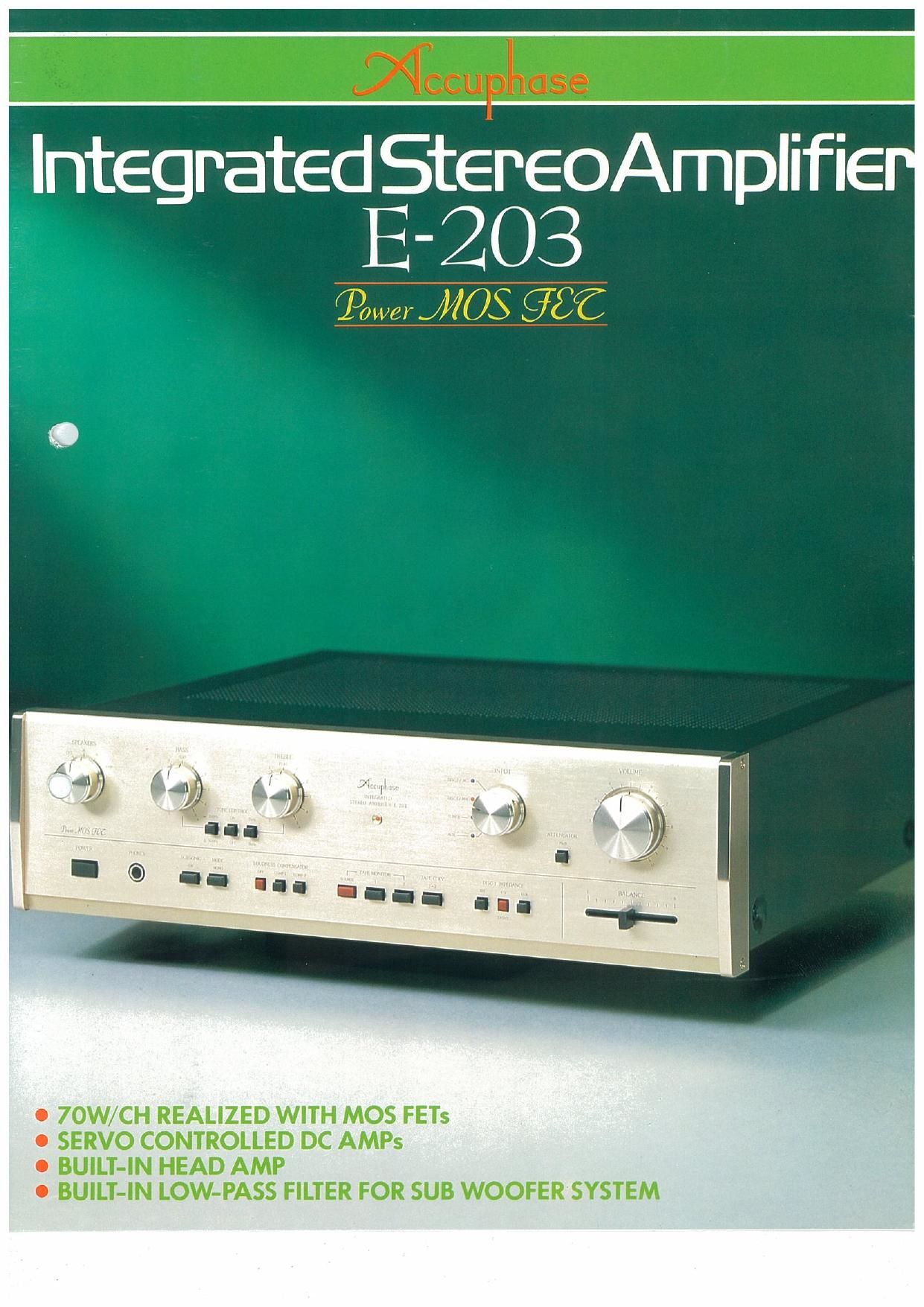
Accuphase E 203 ad

This is the 4 pages manual for Accuphase E 203 ad.
Read or download the pdf for free. If you want to contribute, please mail your pdfs to info@audioservicemanuals.com.

Page: 1 / 4
left right
Accuphase E 203 ad

Extracted text from Accuphase E 203 ad (Ocr-read)


Page 1

O 7OW/CH REALIZED WITH MOS FETs

0 SERVO CONTROLLED DC AMPs

O BUILT-IN HEAD AMP

0 BUILT-IN LOW-PASS FILTER FOR SUB WOOFER SYSTEM

Page 2

Kensonic Laboratory has called upon the highest grade separate
amplifier design technology to create the Accuphase E-203 In-
tegrated Stereo Amplifier. Its power output stages employ MOS
FETs (Metal-Oxide Semiconductor Field Effect Transistors) which
are considered the most advanced, ideal devices for such applica-
tions. They are used in complementary-symmetry push-pull output
stages that give full play to their superior characteristics to produce
afar superior, outstanding sound quality.

The E-203 has a power output of 70 watts per channel (8-ohm
load, 20 - 20,000 Hz, less than 0.01% distortion) which is ample
for even the most spacious hi-fi home listening rooms. It is a pure
DC amplifier which produces practically no sound coloration
because of its special DC Servo Control system for its tone control
sections and power output stages.

One of the main features of the Accuphase E~203 is the extra
rich bass reproduction that becomes a possibility because of its built.
in, low-pass filter network whose output can be fed to separate sub
woofer system. A richer bass emphasis can be obtained byconnecting
monophonic power amplifier and sub woofer to this filter output.

70W/CHANNEL REALIZED WITH MOS FETs

"What is the ideal power output device?"

This question has long been a subject of debate, but ever since the
potentialities of the MOS FET were revealed at the Audio
Engineering Society (U.S.A.I, in May, 1976, it became apparent,
without question, that this active device held the most promise for
the future. However, the birth of high power MOS FETs took a long
time due to technical production difficulties. It was finally realized
here in Japan ahead of the world. As a result, audio amplifier
performance has now entered a new era.

The E-203 employs these powerful MOS FETs. Two of them are
used in a push-pull output stage. and account for the high output
power of 70 watts per channel.

Since the MOS FET has characteristICs which make it easier to
use than bipolar transistors or V-FETs, and also because there is no
notching distortion during high frequency transmission, there is a
significant improvement in treble response. Moreover, its high
frequency characteristics are excellent and effectively confine
harmful TIM (Transient lntermodulatio-n Distortion) to a minimum.

It does not create notching distortion because of its extremely
high input impedance, and also because it is voltage controlled, and
requires very little power from the previous stage. This makes it
possible to utilize a classA driver amplifier stage with the result that
superior characteristics, closer to the ideal class-A operation, can be
realized than with bipolar transistors.

Moreover, the MOS FET has a very high gain equivalent to two
or three stages of directly coupled Darlington Pair amplifier circuits
using bipolar transistors. The number of stages can therefore be
reduced, and superior performance achieved.

The bipolar transistor may seem to have many shortcomings
from the above explanation. It was presented only as a matter of
comparison, however, it is true that a high perfection amplifier can
be made even with bipolar transistors if it is well-disigned.

BUILT-IN LOW-PASS FILTER FOR
SUB WOOFER SYSTEM

Small speaker systems invariably lack sufficient bass response.
Yet, the lower frequency bass region forms the very foundation of
music. A lively, sour-stirring musical reproduction cannot be
realized without sufficient bass.

The E-203 is, therefore, provided with a built-in, lowpass filter
network to which can be connected to a sub woofer system (mono
amp and special woofer) to obtain a very rich, luxuriant bass
response. The low-pass filter network has three, high-side cutoff
frequencies of 50H2, 70Hz and IOOHZ, from which the most
suitable can be selected, depending on the left and right channel
bass response of your speaker systems.

SUB WOUFER SYSTEM

CONTROLLED HIGH-LEVEL AMPLIFIER AND ,
POWER AMPLIFIER STAGES

All unit amps are DC types, with pure DC amplifier design
adopted throughout. Large capacity, direct current blocking ca-
pacitors in the NF loops have been completely eliminated so there is
no sound coloration.

This was accomplished by effectively controlling DC drift which
had been generally recognized as very difficult in high-level amplifier
sections that contain tone control elements, and where switches and
volume control change the value of NF elements.

A new DC Servo Control system was developed to achieve this. It
has effectively eliminated DC drift at the output and has permitted
direct coupling of even the power amplifier stages, as well as pure
DC amplifier operation even when the tone control circuit is ON.

2 DC UNIT AMPS THROUGHOUT- DC SERVO
)

ICL (Input Capacitor- Less) DESIGN

In order to reduce further the tonal coloration effects of
capacitors, the input capacitors of unit amplifiers were also
eliminated. As a result, there is only one capacitor used in the signal
path circuit all the way from AUX and TUNER inputs to the final
output.

- LOW NOISE, WIDE DYNAMIC RANGE HEAD
AMPLIFIER
.0

The input circuit of the Head Amplifier employs ultra-low»noi
transistors in a differential amp circuit, which together with the low
impedance of the NF loop are the reasons for the high S/N ratio of
70dB (at rated input). Any type Moving~coil cartridge can be
connected directly without fear of clipping distortion because of the
wide dynamic range of the Head Amplifier (maximum input voltage
10mV rrns).

.2

. HIGH S/N EQUALIZER AMP

Low noise active devices must be used in the equalizer input
circuit to achieve high S/N ratio, but this alone is insufficient. Low
noise parts and elements must be used as well. Low impedance of
the feedback loop is also most important to obtain low current
noise and thermal-noise.

Class-A operation with large current flow in the final equalizer
transistors has lowered the impedance of the NF loop, and greatly
reduced the noise generated at the differential input circuit. The
S/N ratio is 77dB (at rated input) which is close to the theoretical
limit.

HIGH PERFORMANCE POWER
TRANSFORMER WITH C-l CORE

A high efficiency, low flux leakage, Cal shaped core type power
transformer is used. It is the same type as those AC power line trans-
formers on electric posts which can readily meet the widely chang-
ing load requirements for electricity in homes.