Accuphase c 7 owners manual

This is the 3 pages manual for accuphase c 7 owners manual.
Read or download the pdf for free. If you want to contribute, please mail your pdfs to info@audioservicemanuals.com.

Page: 1 / 3
left right
accuphase c 7 owners manual

Extracted text from accuphase c 7 owners manual (Ocr-read)


Page 1

mccuphase C-7

MOVING COIL CARTRIDGE HEAD AMPLIFIER
INSTRUCTION MANUAL

INTERCONNECTION

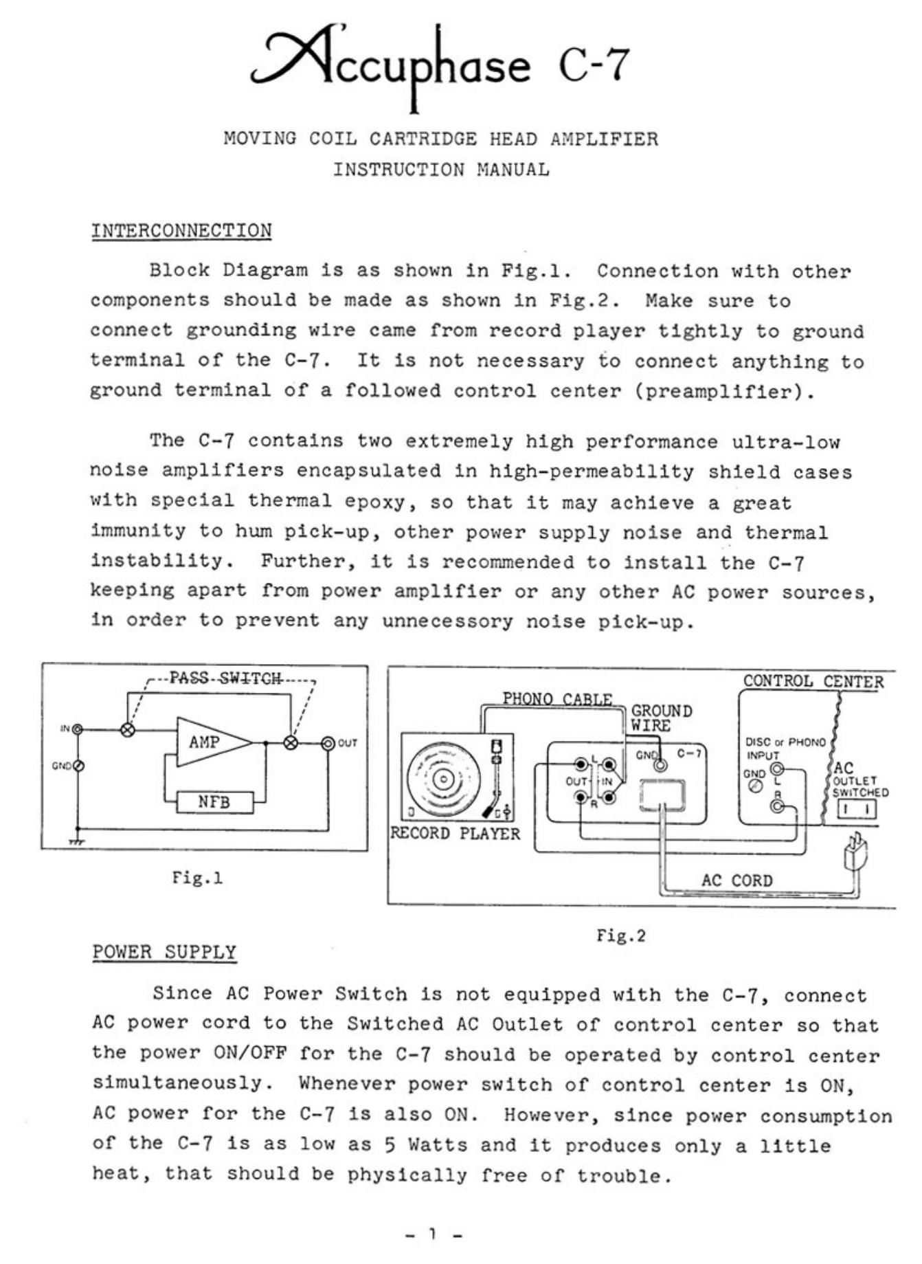
Block Diagram is as shown in Fig.1. Connection with other
components should be made as shown in Fig.2. Make sure to
connect grounding wire came from record player tightly to ground
terminal of the 0-7. It is not necessary to connect anything to
ground terminal of a followed control center (preamplifier).

The C-7 contains two extremely high performance ultra-low
noise amplifiers encapsulated in high-permeability shield cases
with special thermal epoxy, so that it may achieve a great
immunity to hum pick-up, other power supply noise and thermal
instability. Further, it is recommended to install the C-7
keeping apart from power amplifier or any other AC power sources,
in order to prevent any unnecessory noise pick-up.


r' "PASS-SUITCH-«u: CONTROL CENTER
SWITCHED

. L AWGN$ 0-1
" OUT {IN 7-'-
r;
9 «- l I

RECORD PLAYER 1
Fig.1 1 AC coan ii

Fig.2

POWER SUPPLY

Since AC Power Switch is not equipped with the C-7, connect
AC power cord to the Switched AC Outlet of control center so that
the power ON/OFF for the C-7 should be operated by control center
simultaneously. Whenever power switch of control center is ON,
AC power for the c-7 is also ON. However, since power consumption
of the C-7 is as low as 5 Watts and it produces only a little
heat, that should be physically free of trouble.

Page 2

Make sure to turn the volume control of control center down
whenever AC cord of the 0-7 is plugged or unplugged to AC Outlet
under the condition of operation, in order to prevent shock noice
coming out.

SWITCHING NOISE WHEN OPERATING PASS SWITCH

Total gain comes to as high as 100 dB (10,000 times)
throughout headamplifier input to power amplifier output. As
a result, even a very small amount of noise, such as function
operation noise, is amplified to big noise and fed out from
speaker. In the muting circuit employed will eliminate sharply such a noise.
However, though it may cause sometime a little noise when
operating PASS Switch, it should be absolutely free from any
trouble.

CHANGING OF PHONO CARTRIDGE

Whenever a phono cartridge is connected or disconnected,
make sure to turn the volume control of control center down in
order to prevent shock noise coming out.

OUTPUT IMPEDANCE 0F PHONO CARTRIDGE V.S. INPUT IMPEDANCE OF
HEADAMPLIFIER

Input impedance of head amplifier is considered to be
a load impedance of phono cartridge. If presuming phono
cartridge to be a generator, such load impedance should not
disturb generators proper motion. This resembles relation
between output impedance of amplifier and impedance of speaker.
Therefore, it is required as a general rule that the load
impedance of phono cartridge should be more than several
times as high as the output impedance of phono cartridge.
Through a great deal of careful listening test on any available
Moving Coil Cartridge, we decided the input impedance of fixed
100 Ohms. It matches to the output impedance of every
available MC cartridges, such as from 2 - 3 Ohms of Ortofon
types to "0 Ohms of EMT types.