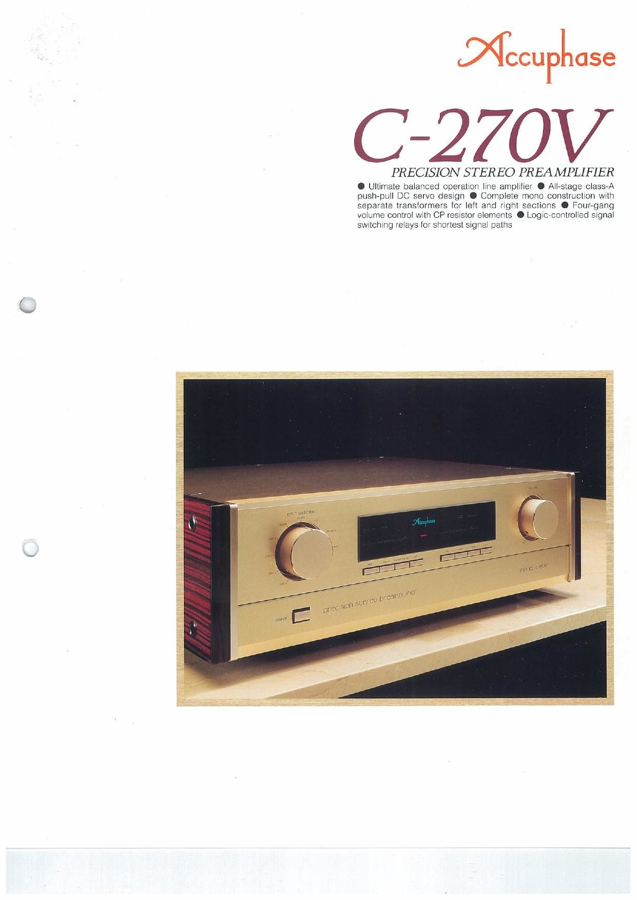
Accuphase C 270 V Brochure

This is the 6 pages manual for Accuphase C 270 V Brochure.
Read or download the pdf for free. If you want to contribute, please mail your pdfs to info@audioservicemanuals.com.

Page: 1 / 6
left right
Accuphase C 270 V Brochure

Extracted text from Accuphase C 270 V Brochure (Ocr-read)


Page 1

(\

MCCUPLOSG

C-27OV

PRECISION STEREO PREAMPLIFIER

0 Ultimate balanced operatron llne amplrfrer O All-stage class-A
pushepull DC servo design 0 Complete mono construction with
separate transformers lor left and right sections 0 Four-gang
volume control with CP resistor elements 0 Loglc-controlled signal
sthching relays for shortest signal paths

Page 2

As exemplified by the C-280V. the Accuphase
policy for preamplifier development has been
to pursue performance and sound quality
without any compromise. The C-ZBOV is
based on the same strategy. Six years after
the introduction of the original (3-270. it is a
further matured product, where every aspect
has been redesigned. The C-270V does not
contain a phono equalizer stage. but it fea»
tures a line amplifier section developed
specifically for optimum performance with
high-level sources such as CD players.

About 10 years have elapsed since Accu-
phase introduced the balanced signal trans-
misSion principle to the realm of home-use
audio components. and many high-end
models nowadays include this feature. The
line amplifier of the C-270V is based from the
ground up on balanced operation. providing a
dedicated direct-coupled section for bale
anced and unbalanced output without the
need for transformers. The input stage em-
ploys a newly developed FET differential
push-pull arrangement that provides high in-
phase signal rejection, This type of circuit is
ideally suited for balanced amplification. The
output section features a symmetrical bridged
feedback design for true balanced output. A
separate circuit is provided for the unbal-
anced output lacks. In all, the C-27OV is the
optimal highllevel preamplifier.

Two important tasks of a preamplifier are
input source selection and volume adjust-
ment. The C-27OV switches sources with her-
metically sealed nitrogen gas filled relays
operating under logic control and arranged to
allow the shortest possible signal paths. This
prevents signal degradation and noise intru-
sion. and also dramatically improves long-
term reliability. For the volume control, the
same fouregang CP (conductive plastic) reSis-
tor as in the C-280V is used. it features an in-
novative design approach in that the reststor
element assembly rotates while the contact
brush remains stationary. This drastically
reduces the number of metal contact points.

Ultimate Line Amplifier Featuring Flawless Balanced Operation.
Unit Amplifiers Powered by Wide-Range,

Low-Impedance Dedicated Power Supplies.

Mono Construction Throughout, with Separate

Left/Right Power 'ITansformers.

Four-Gang Volume Control with CP Resistor Elements.

to eliminate any possibility for sound quality
deterioration.

Every unit amplifier is housed in a sturdy
aluminum enclosure. and the dualechannel
mono construction of the 8 mm thick chassis
prevents unwanted electrical or mechanical
interaction between channels. All signal paths
on the PCBs are gold-plated and wiring is
kept to a minimum. In each and every detail.
the C-27OV is built to deliver top-quality audio
performance.

Ultimate Balanced Line Amplifier
Accuphase has long been a proponent of bat-
anced signal transmission. The C-270V. like
the C-280V. realizes this principle to the
fullest. In balanced signal transmission. two
identical signals are transmitted simulta-
neously with inverted phase and combined at
the receiving end. thereby canceling out
common-mode noise components. Even long
cable runs do not affect the quality of the
signal. which is why the principle is exten-
sively used in professional applications and
broadcast studios etc.

Recently, even in ordinary households.
there are many possible sources of electrical
and air-borne high-frequency noise which can
enter the cables of audio components and
cause sound quality degradation. Balanced
signal transmission reliably guards against
this danger. making it an important require-
ment for true high fidelity,

The line amplifier of the C-270V was devel'
oped specifically to get the full benelit of bat-
anced operation, Fig. 2 shows the principle of
this amplifier. in balanced operation (a). three
differential amplifiers are active, AMP1 for the
input and AMP2 and AMP3 for the output.
AMP1 accepts the (+) and (e) Signals, ampli-
fies them and supplies them to AMP2 and
AMP3. These two amplifiers employ cross-
feedback loops, with part of the output of one

amplifier going to the input of the other. This
results in a (+) (e) symmetrical signal output
with low impedance. In the case of (b). when a
component with unbalanced output is con-
nected. it suffices to simply ground one side
of the signal at the input and output.

All-Stage Class-A Push-Pull Dc Servo Con-
struction

The 027W possesses separate line ampli-
fiers for unbalanced and balanced output.
Fig, 3 shows the circuit diagram of the ampliv
tier for unbalanced signals. The input stage _
employs a constant-current load cascodp
bootstrap source follower arrangement tha
drives a symmetrical balanced differential
push-pull emitter follower amplifier with high
in~phase signal rejection. The output section
is also a symmetrical cascode push-pull
emitter follower type. Fig. 4 shows the circuit
diagram of the amplifier for balanced signals.
The input section is similar to that of the ampli-
fier for unbalanced signals. with an added
balanced output amplifier. Like in the C-280\/.
an inverting and non-inverting amplifier are
used. with bridged feedback for balanced
operation, Both the inverted and non-inverted
output signals are totally isolated from the
ground,

All unit amplifiers employ measuring-in-
strument quality le and DC servo circuitry
without any capacitors. The result are out-
standing temperature characteristics and
stable operation with any kind of input signal.

Complete Mono Construction with Sepa-
rate Transformers for Left and Right Sec-
tions

The power supply section also has been \qu
designed. Two sets of power supply trans-
formers and filtering capacitors preclude any
possibility of electrical interaction between the
channels. In addition. each unit amplifier has
its own wide-range voltage regulator circuitry.
to eliminate possible interference between
stages.

COMPLEVE uunceo AMPUFIER

on @ EALANCE ATT. voLuMe

TUNER ©_.
Liner 9-»

4

LINE: 9-. E

LiNEa @-. S

3

LlNEd @-. g

e

3

co BALANCED 4
LINE BALI
LiNe EAL. 2

HeAuPMoNe AMPLIFIER

Fig. 1 Circuit block diagram of C-27OV (one channel)

muuceu
ourvur r

BALANCED
ourFur z

_ uNBAmeeD

ourvur r

. UNBALANCED

OuYPUY 2
Newman:
ourPuT


Inverted .
input

Nun-inverted
Input

_ Non-inverted
output

Source component
such as on player

Power nmpilrier

b) when connected to unbalanced input or output equipment

Fig. 2 Principle of the balanced transmission