Accuphase C 240 Brochure

This is the 4 pages manual for Accuphase C 240 Brochure.
Read or download the pdf for free. If you want to contribute, please mail your pdfs to info@audioservicemanuals.com.

Page: 1 / 4
left right
Accuphase C 240 Brochure

Extracted text from Accuphase C 240 Brochure (Ocr-read)


Page 1

WCCUPLCISG
C-24O

PRECISION CONTROL CENTER

Page 2

The C-240 is a high-gain, Control Center Amplifier which symbolizes
the combined aggregation of Accuphase audio technology. It has a total
gain of 86dB and includes a Head Amplifier for Moving coil cartridges
and a full-fledged Headphone Amplifier.

Besides providing all the standard functions of the most versatile
Control Center, the C240 has wide ranging frequency response control
capability which is truly outstanding. This important feature not only
permits the most delicate tonal adjustments to satisfy individual tastes,
but even allows alteration of phono cartridge characteristics for im-
proved fidelity.

The basic circuitry consists of the complementary-symmetry,
Class-A pushrpull driven DC amplifier circuits in every stage, which is an
Accuphase original. Only the highest rank active devices available are
used wherever they may affect sound quality, and newly developed
devices have been introduced where necessary.

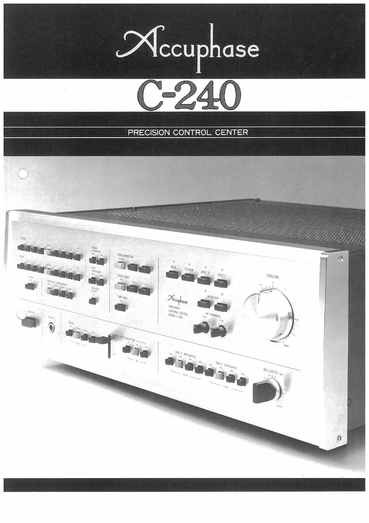
The panel layout which is dotted with Push Switch Buttons is
indeed unique as the photo shows. In fact, it is completely different
from ordinary Control Center front panels, and operation may seem
complicated at first glance to the uninitiated. However, the exact oppo-
site is true for operational ease was the main factor in designing this
new panel function face which represents another significant advance
in human engineering. Actual operation proves this immediately as any
one will realize that the direct, speedy control of push-button switches
cannot be duplicated with rotary switches.

I UNIQUE FRONT PANEL

This unique front panel is composed of four rotary knobs, one lever
switch and, indeed, a total of 57 push switches. However, there is no
feeling of complexity since they are arranged in a most orderly manner
according to function, as planned in initial design. Rather, the feeling of
instantaneous fingertip control that cannot be experienced with rotary
switches becomes immediately apparent since unnecessary positions can
be jumped, and necessary function positions set immediately.

This is especially the case with input selector buttons. They provide
"feather touch" input source selection electronically by activating
electronic circuits which control the relays.

The advantage of electronic control is also utilized for Head
Amplifier switching which is linked with DISC I and DISC 2 cartridge
selection with a memory feature that automatically handles respective
ON/OFF switching.

Also parallel dual contact points are built into all push switches
and relays in order to minimize contact resistance which can greatly
affect sound quality and durability.This extravagant measure further
ensures highest stability and long life performance.

COMPLEMENTARY-SYMMETRY, CLASS-A PUSH-

PULL DRIVEN, ICL TYPE, DC AMPLIFIER

ClRCUITS IN EVERY STAGE

The Accuphase C-240 employs the extravagant complementary»

symmetry, Class-A push»pull driven DC amplifier circuits all the way
from the Head Amplifier input to the final output, including the
headphone amplifier. Although this system requires almost twice as
many parts as ordinary circuits, it possesses superior openrloop
characteristics, including especially excellent linearity. Therefore, it
requires a minimum of NFB application and accounts for its outstand-
ing low distortion ratio. As a result, great improvement was made in

preventing TIM (Transient lntermodulation Distortion) which causes
sound quality deterioration.

All unit amplifiers are pure DC amps. High capacity DC blocking
capacitors have been completely eliminated from the NF loops, as well
as all input coupling capacitors. llCL system: Input Capacitor-Lessl.
The removal of these capacitors has eliminated the possibility of sound
coloration. During phono reproduction, the cartridge is directly con»
nected to the amplifier and this permits enjoyment of a higher quality
disc reproduction sound.

DYNAMIC RANGE, LOW-NOISE, MODULAR~TYPE
HEAD AMPLIFIER

The Head Amplifier is a 26dB gain flat amplifier. Four RETs (Ring
Emitter Transistor) that were especially developed to handle low level
input signals are employed in the first stage push-pull differential
amplifier circuit. Their use has contributed greatly to the head
amplifier's low noise characteristic. Moreover, the large current used to
drive the output stage has made in possible to lower both the output
and feedback loop impedances, which are additional reasons for the
high S/N ratio of 74dB, a value that is close to the theoretical limit.

Clipping in Control Amplifiers can seriously deteriorate sound
quality. In order to provide sufficient dynamic margin for 0.5mV cl"
cartridges without danger of clipping, the C-240 is designed to handl
maximum input voltage of 20mV without clipping, input impedance is
a fixed 100 ohms when the head amplifier is used.

The head amplifier block is encased in a module to prevent moisture
penetration and assure stable operation against any possible humidity
conditions.

4 HIGH S/N EOUALIZER AMP COMPLETELY
PREVENTS SOUND COLORATION

Figure 1 shows the 36dB equalizer amplifier section of this unit.
Following the input FET buffer amplifier, it is comprised of comple-
mentary-symmetry, push-pull amplifier circuits in every stage. FIETs are
used for 014 and 015 at the equalizer output for superior high
frequency power amplification. A very high S/N ratio of BGdB, which is
close to the theoretical limit is achieved because of the low output
impedance and low feedback loop impedance made possible by the
large driving current of class-A operation. Another contributing factor
is the high forward transconductance of the FETs lHigh Gm FETsI in
the input buffer amplifier, The equalizer amplifier is equipped with a
ng lgate-to-drain capacitance) Cancelling Circuit to prevent high
frequency distortion that can be caused by Gate-to-Drain capacitance
of 01 in the buffer amp section. It is the usual practice as a prevention
measure to use a cancelling capacitor between Gate and Source, but it
can cause sound coloration since this input circuit deals with phor
cartridges that contain reactance components. The ng CancelliU
Circuit built around Q3a,03b, DI and D2 very effectively prevents high
frequency distortion and sonnd coloration,

5 DC SERVO CONTROL HIGH-LEVEL AMPLIFIER

It is customary in high»level amplifiers to adjust tone by varying the
capacitance and resistance of the NF device. In such cases, a small DC
current is created in the amplifier output which can cause a large pulse
type shock noise. A DC blocking capacitor is normally used to prevent

uurm

lam

Fig. 1. DIAGRAM OF EQUALIZER AMPLIFIER

Fig.2. DIAGRAM 0F SERVO CONTROLLED HIGH-LEVEL AMPLIFIER