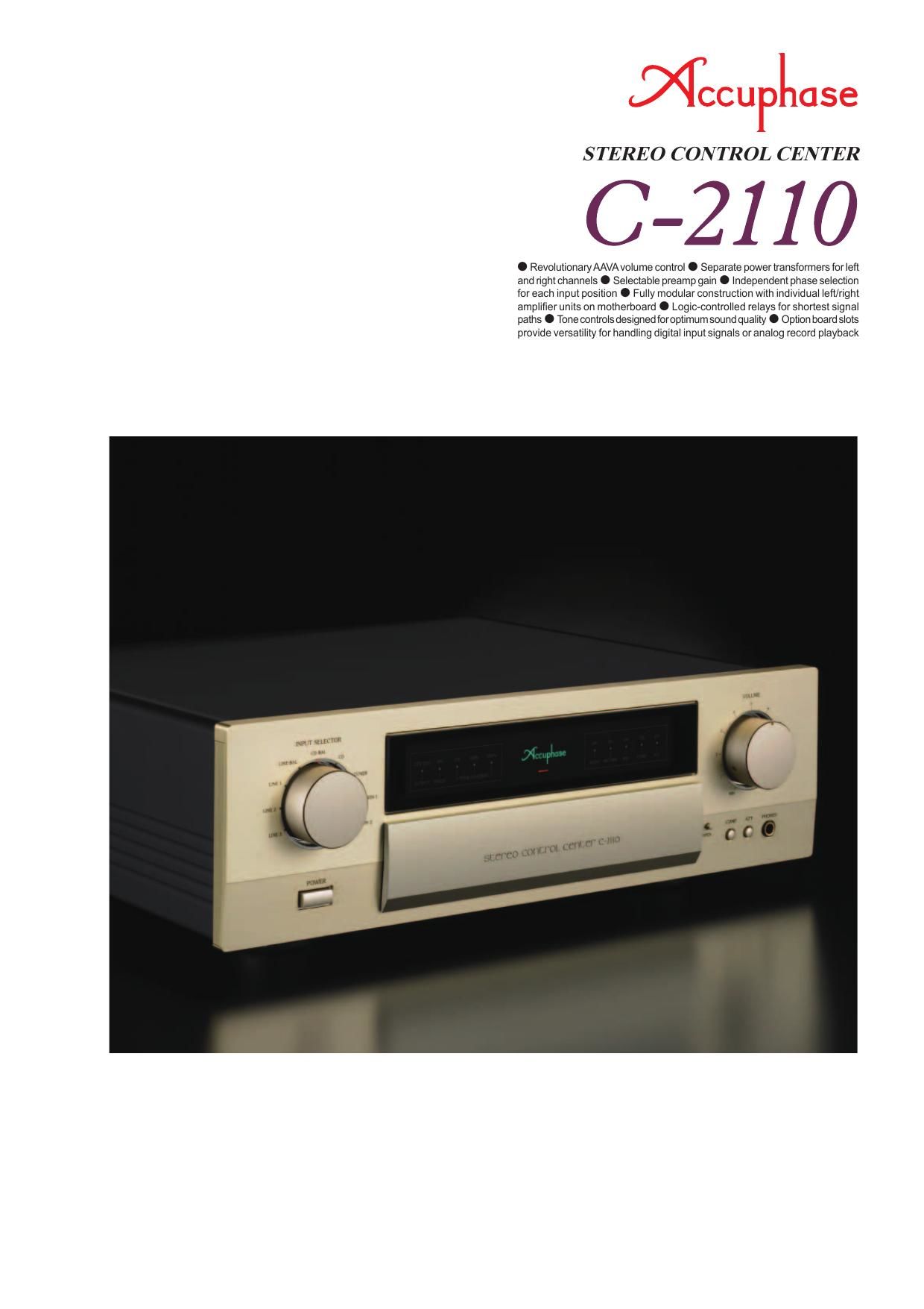
Accuphase C 2110 Brochure

This is the 4 pages manual for Accuphase C 2110 Brochure.
Read or download the pdf for free. If you want to contribute, please mail your pdfs to info@audioservicemanuals.com.

Page: 1 / 4
left right
Accuphase C 2110 Brochure

Extracted text from Accuphase C 2110 Brochure (Ocr-read)


Page 1

Further improved AAVA volume control provides ultra-smooth action -ˆ’ Adjust the listening level without any losses in sound quality or perform- ance. Complete dual mono construction features separate power supplies, plus separate AAVA unit ampliļ¬ er modules on a motherboard. Individual control of phase for each input position. Option boards enable reproduc- tion of digital input signals and high-grade playback of analog records. Ever since being introduced in the model C-2800, Accuphases ground-breaking AAVA (Accuphase Analog Vari-gain Amplifier) volume control has undergone further reļ¬ nements, reļ¬‚ ecting accumulated technical know-how. The result has made an excellent idea even better, and it has helped Accuphase preampliļ¬ ers maintain their position as undisputed leaders and reference products both in terms of sound quality and performance. The C-2110 is a successor to the model C-2000. It inherits advanced design technology from the C-2810 and C-2410 and features AAVA volume control with the same outstanding speciļ¬ cations and conļ¬ guration but further augmented circuitry. AAVA is a new kind of volume control that assures excellent sonic Operation principle of AAVA in C-2110 performance by integrating the amplification and volume control tasks and eliminating all mechanical contact points from the signal path. The fact that the music signal no longer has to pass through any variable resistors brings a number of distinct design advantages and enhances sonic purity. Another beneļ¬ t of AAVA is that only highly reliable electronic components are used, ensuring that the outstanding performance and sound quality of the ampliļ¬ er will remain undiminished for many years to come. In actual operation, the volume knob on the front panel which is only used for position detection has the same feel as on a conventional ampliļ¬ er. The power supply section of the C-2110 employs separate transformers, while ļ¬ ltering capacitors and other parts of the power supply are also duplicated for left and right. Whats more, the AAVA circuitry, balanced output circuits, and other unit ampliļ¬ ers are also entirely separate for the two channels, arranged on a high- quality motherboard. This fully monaural construction prevents unwanted crosstalk and interaction both on the electrical and the physical plane. Most of the internal circuitry of the C-2110 is devoted to AAVA, but there are also tone controls, a loudness compensator, recorder connection support and other convenient features. The PHASE button lets the user specify the phase setting for each input position separately, and EXT PRE connectors offer further enhanced ļ¬‚ exibility. The overall result is a versatile analog preampliļ¬ er of immense appeal. Further Improved AAVA (Accuphase Analog Vari-gain Ampliļ¬ er) Volume Control AAVA is a radically different volume control principle that eliminates all variable resistors from the signal path and provides top-notch performance and sound quality. Because the music signal is not affected by changes in impedance, high signal-to-noise ratio and low distortion are maintained at any volume control setting. -–  Volume control resolution AAVA adjusts the listening volume by means of 16 weighted V-I converter ampliļ¬ ers which are controlled by current switches. The number of possible volume steps set by the combination of these converter ampliļ¬ ers is 2 to the power of 16 = 65,536. -–  Input buffer amps use 5-MCS topology One of the factors that have a bearing on possible noise in an AAVA arrangement is the input buffer. By connecting ļ¬ ve high-performance amps in parallel, drive capability under low-load conditions has been improved, and excellent S/N ratio is assured. -–  AAVA ensures high S/N ratio and uniform frequency response Unlike conventional volume controls, AAVA does not introduce a change in impedance at any volume setting. Consequently, there is no deterioration of S/N ratio and frequency response remains totally uniform. The beneļ¬ ts are especially apparent at settings that correspond to normal listening levels, because the sound remains perfectly transparent and the tonal quality is not altered in any way. -–  No more left/right tracking differences or crosstalk Because AAVA is an electronic circuit employing ļ¬ xed-value resistors, there is virtually no left/right tracking error also at low volume levels. Since channels can be kept separate, crosstalk also does not present a problem. -–  AAVA means analog processing The AAVA circuit converts the music signal from a voltage into a current, switches gain by means of current switches, and then reconverts the current into a voltage. The entire process is carried out in the analog domain. -–  Same operation feel as a conventional high-quality volume control The volume control knob position is detected by a dedicated CPU which in turn selects the current switches for AAVA operation. Operating the knob therefore feels exactly the same as with a conventional control, and as before, operation via the remote commander is also possible. -–  Attenuator and balance control also implemented by AAVA The functions of the attenuator and the left/right balance control are covered by the AAVA circuit as well, eliminating the need for additional circuit stages. Keeping the conļ¬ guration simple helps to maintain high performance and sonic purity. Input music signal The music signal is converted into 16 types of weighted current by V-I (voltage - current) converting ampliļ¬ ers [1/2, 1/2 2, ... 1/2 15, 1/2 16]. The 16 currents are turned on or off by 16 current switches, and the combination of switch settings determines the overall volume. The switching operation is controlled by a CPU according to the position of the volume control knob. The combined signal current forms a variable gain circuit that adjusts the volume. Finally, the combined current is converted back into a voltage by an I-V (current - voltage) converter. AAVA operation principle AAVA assembly includes boards with separate modules for left and right input buffers, 16 V-I converters + cur- rent switches, current adding circuitry, and I-V converters, as well as the CPU board for AAVA control. -–  Simple circuit conļ¬ guration AAVA uniļ¬ es the ampliļ¬ er and volume control functions, resulting in a circuit that is electrically very simple. Long-term reliability is excellent, with performance and sound quality that will remain unchanged also after prolonged use. + Conversion into current with 16 weighting stages (1/2 - 1/2 16) CPU detects position of volume knob and operates current on/off switches according to knob position Volume knob is turned and position is detected Current values are added Reconversion of current into voltage 16 current switches (65,536 possible combinations) INPUT OUTPUT GAIN I-V Converter CPU Volume Balance Attenuator BUFFER BUFFER V-I Converter

Page 2

OFF/EXT INV OUTPUT PHASE LOUDNESS COMPENSATOR: ON 10 100 1k 10k 100k 18 16 14 12 10 8 6 4 2 0 -2 -4 -6 Balanced input and output connectors Unbalanced input and output connectors Loudness compensator characteristics EXT PRE function and phase se- lector button, with LED indicators Gain selector -–  Dual mono construction with separate left and right transformers and separate circuit modules mounted on a board. -–  Logic-controlled relays assure high sound quality and long-term reliability. Strategically placed relays ensure optimum signal ļ¬‚ ow and prevent degradation that could occur if the signal has to travel a long way for input and output connection and function switching. -–  Individual phase control for each input position The setting of the PHASE button is memorized for each input separately, and the LED indicator shows the respective status: lit (phase inverted) or out (normal phase). -–  Selectable preamp gain The overall gain of the preampliļ¬ er can be set to 12 dB, 18 dB, or 24 dB. -–  Dedicated headphone ampliļ¬ er optimized for sound quality -–  EXT PRE function allows use of external preampliļ¬ er -–  Versatile arrangement of balanced and unbalanced input and output connectors -–  Two option board slots on rear panel for system expansion -–  More versatile features: - Provisions for recording and playback with a recorder - Loudness compensator augments bass impact at low listening volume - Attenuator (-“20 dB) -– Supplied remote commander RC-200 Allows volume adjustment, input source switching, and other operations. Frequency in Hz Response in dB LOUDNESS COMPENSATOR: ON