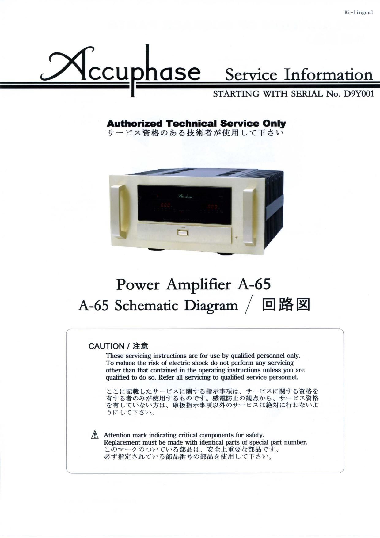
This is the 25 pages manual for Accuphase A 65 Service Manual.
Read or download the pdf for free.
If you want to contribute, please mail your pdfs to info@audioservicemanuals.com.
EXPLANATION OF SURFACE PARTS
(fiifififiufin)
* Front Glass
7117”!” §X
(172-0156-03)
[
Heat Sink
l t~+977
Handle A (240*0098i00)
$13:— A ’
(132 0118 03) Hexa Hole Screw
— 77 _ _,‘ 7 " fifilflfiéVMMV
\ fl 7 M5><12: 12pcs_
(631—0011—10)
‘7 Handle B
9 77 , 333 B
' '(240~0097—02)
_~ Spacer
r. a ‘ 7\’\n ”4f
7 ' «'\ (2501336703)
Hexa Hole screw
*igifilel .7" , - ‘ fififlfi‘énfliv“
7, , M4><82 10pcs.
(l34i0169’02) (631*0019i00)
P hib tt f POWER
5”?” fightilyyo” or * Push-button for OPEN
(23870023700) (388-5061-13) 7 “ml W
Power Push Switch (388-0402_04)
I" ‘7~7w 771147?
(354—1025—00)
Top Plate Assembly
l~77°7° wt Ass’y
(150-0095-02A) Front Panel Assembly
*Punching Metal 7117M“ 7M Ass' y
n“ 71W )‘WV/chs. (130—0209—01)
Heat Sink (170—0980—03) _ /
Hwy? ,, /
(24070098700) \ \
\ x a l
.__\
Handle B Handle A
336': B $13}? A
(24070097702) (132—0118703)
Spacer
MW?
(250*1336i03)
Hexa Hole screw f‘ 7“
fififxfiauwrf ———, \ 7
M4X8210pcs. “ , L // i 777/, r: ‘ ' 'Knob for GAIN
(631v0019—00) 7 I p, .773
« x ‘ \ (384~1405—04)
/ ‘ ‘ -\
Knob for METER Botton} Plate Pushibutton for INPUT
773 Pu hibutt n f r HOLD TIME “I” H 7'37”?”
(1384—1405704) 7., 3m? ”0 0 (15570099702) (389—5077—13)
(389-5077-13)
*lllll'k parts not suppllod
Y-QflfllifltfitflfikifiA:
FRONT VIEW (Sub-chassls slde)
(«r 7‘ 9 v — 91mm I)
LED / 021,22
(SDPWBDGOBOiJ)
l
l
l
l
l
l
J
LED Assembly/2pcs.
(723—0155—00)
Hold Time board
Display Assembly
if“ 417" IMAss’ y
(723*0154fi0)
,,,,,,,,,,,,,,,,,, Gain Sw. side
APower Push Switch
13940;?
(354*1025‘00)
Link/9V7
(251’9021’04)
Back Vlew of Front-Panel Assembly
0
(7 n y |‘/\*lbafibfil)
*Panel Name Plate Indicator
A"$W?—A7'V“l 479v47~9
(180-1108-03)
Gain Switch Assembly
V 4V14'fiAss' y
(71670850~00)
Push-button for OPEN 1
7” y‘hf 5V / #739 7M 1'7" ‘/
(388—0402—04) Front Glass
7DVlfl°7X
(172’0156’03)
Fixed Bracket
if flflifififi-
(247-1200-03)
l
—i
, ’lriw fl
Attention mark indicating critical components for safety.
Replacement must be made with identical parts of special part number.
:mv—amdwrw6fi&n\fétifikmafifi
fofifléhru\6¥%&§%mafisfizil§m I/CTé u,
Push Button for POWER
7‘ 791$v 5'7
(388-5061-13)
Pushrbutton Frame
(11370143704)
*Coil Spring
(285*1022~04)
*Washer
(637-0043-04)
E-ring
(647*1055400)
A
4
(17379105,03)
Meter Switch
Assembly
)‘rflxifl‘Ass' y
(716—0849—00)
Pan Head Screw With
Spring
i£’
Push Button for
HOLD TIME/GAIN
7" 7911557
(389-5077-13)
*Push-button Frame
(11370111,14)
* Coil Spring
(28571023704)
1k nnll‘KIIIItS Ila! Slllflpliflll
vfiflflufifiw¥ith