Accuphase A 50 Brochure

This is the 6 pages manual for Accuphase A 50 Brochure.
Read or download the pdf for free. If you want to contribute, please mail your pdfs to info@audioservicemanuals.com.

Page: 1 / 6
left right
Accuphase A 50 Brochure

Extracted text from Accuphase A 50 Brochure (Ocr-read)


Page 1

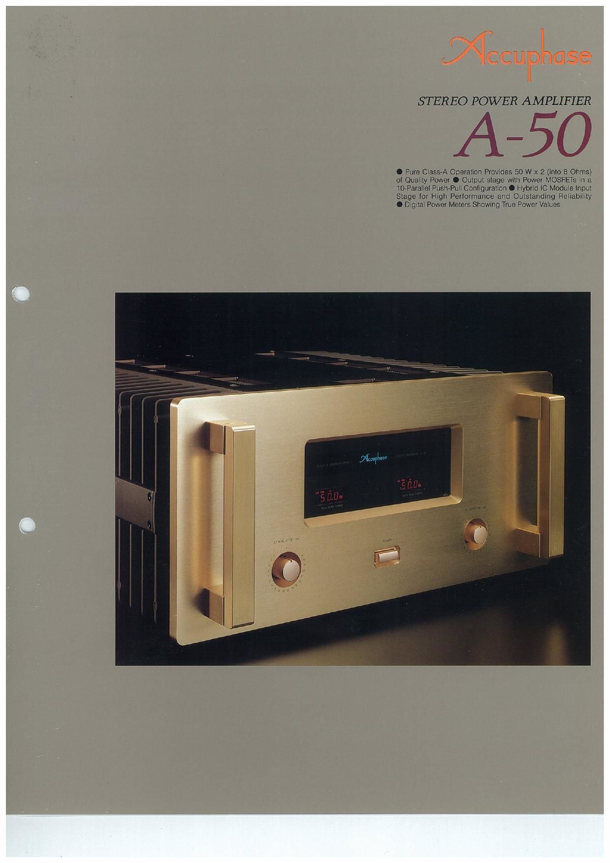
STEREO POWER AMPLIFIER

50

0 Pure Class A Operation Provides 50 W x 2( (into 8 Ohms)
oi Quahty Power 0 Output stage with Power MOSFETs rn a
10-Parallel Push-Pun Configuration 0 Hybnd [C Module rnpul
Stage for High Performance and Outstanding Reliabrllty
I Digitar Power Meters Showrng True Power Values

Page 2

The A-50 is truly a genuine class-A operation
stereo power amplifier built by Accuphase. without
any compromise, by pursuing its ideal for repro-
duced music. Thus, Accuphase incorporates its
audio technologies that have been accumulated
since its foundation as well as the highest grade
electronic devices that are available today.

The advantage of the class~A amplification
method is that power fed from the power supply is
always constant, regardless of the presence of
musical signals or not. This means that the ampli-
fier exhibits high stability, while being subjected to
no external interference, Thus, the amount of heat
generated from the output stage becomes ex-
tremely high. In general, the power consumption
of any class-A stereo power amplifier with a rated
output of 50W is approximately 200W (about 350W
in the case of the A50), which is dissipated as
heat. To counter this heat problem. the A60
employs an exceptionally large heat sink for both
the left and right channels to enhance the effect of
heat dissipation, thereby eliminating any trouble
due to the concentration of heat in the internal cir-
CUitry.

The output power per channel of the A-50
becomes as high as 400W at a t-ohm load (actu-
ally measured value), 2OOW at a 2-ohm load.
100W at a 4-ohm load. or 50W at an 8-ohm load.
Thus, the output power can produce an ideally
linear output value despite the fluctuation of the
load impedance of a speaker system. For this
reason. the A-50 is capable of large output opera-
tion even when a low-impedance loudspeaker is
connected. This amplifier never appears to be
lacking power, having the capability to handle
occasional high pulse music signals, Its clipping
level is factory-set to approximately 100W at an 8-
ohm load.

For its output stage. the A-SO employs power
MOSFETs that have an established reputation for
their contribution to excellent sound quality and
performance reliability. Driving 10 pairs of these
field-effect transistors in a parallel push»pull circuit
configuration, the A60 can maintain stable opera-
tion even with loads having an extremely low
impedance.

The input stage of this power amplifier is a bal-
anced differential input type in a pure complemena
tary push-pull configuration, which is an Accu-
phase original. This makes it possible to provide
for not only a directly connected balanced trans-
mission, but also a direct connection even in the
case of normal unbalanced signal transmiSSion
without resorting to any conversion circuit. This is
done by connecting one input side of a normal un-
balanced signal transmission to the ground.
Thanks to this input circuit configuration, there is
no difference in the quality of sound between the
balanced and unbalanced inputs. Also employed
in this input circuit is Accuphases original hybrid
module, with all FETs, transistors, and le
mounted on an alumina ceramic substrate. This
hybrid module technology makes it possible to
secure high performance, high reliability. and ex-
tended stability without being affected by thermal
changes.

The power supply unit of the A~50 consisting of
a power transformer and filter capacitors is a
supply source for all energy, If an amplifier has an
inadequate power supply margin. it is apt to have
problems. not only in the quality of sound, but also
with its basic performance characteristics. De-
spite the A»50s output capacity of 2 x 50W/8
ohms, the power transformer used is a toroidal coil

Pure Class A - The Sound of Excellence. Enjoy Music t1
Power MOSFET Devices in the Output Stage in a 10-Par
Even at Load Impedances as Low as One Ohm.

Enjoy 50 Watts of High-Quality Power per Channel (into
as Monophonic Power Amplifier Delivering a Stunning 2

type with a power capacity as large as approxi-
mately 1.000VA and the two lilter capacitors em-
ployed are very large capacitance types. Each of
them has a rating of 56.000uF (electric charge ca-
pacitance of 3.5 coulombs). The transformer has
been housed in an aluminum die»cast enclosure.
which is additionally filled with a resin having an
excellent vibration-suppressing coefficient of elas-
ticity. This measure successfully isolates the
power transformer completely from external elec-
trical and mechanical interference.

The digital peak power meter of the A-50 dis-
plays a true power value. The meter first detects
the current and voltages and then calculates the
power value with a built-in analog multiplier. The
output will be further processed by a microcomr
puter. which incorporates an A/D converter to in-
dicate the true
power value of the
constantly chang-
ing musical sig-
nals. This digital
power meter can instantaneously read the impe-
dance of the speaker which varies compiexly
along with different frequencies to display the true
power value. The power supply for the digital
power meter has its own exclusive transformer to
eliminate any adverse effect to the amplifier or-
cults.

Guaranteed Linear Power of 200W/2 Ohms.
toowm Ohms, or 50W/8 Ohms per Channel
thanks to Power Unit with Power MOSFETs in
10-Parallal Push-Pull Configuration.

Fig. 1 is a circuit diagram illustrating the amplifier
output stage of the A-50. This output stage fea.
tures an extravagant circuit configuration in which
10 pairs of power MOSFETs are parallel-con-
nected for each of the N and P channels (05. 05.
024 for the N channel and 07, 09. 025 for the
P channel). Because the permissible power loss is
120 watts per MOSFET employed. the power
burden per parallel pair of the MOSFETs becomes

only 5 watts. This means that the amplifier can use
a small power range of MOSFETs. which have ex-
cellent linearity. In the pure classrA amplification
operation of the A-SO, a large current always flows
through its circuitry. but thanks to this circuit con-
figuration. the current becomes only 1/10 and thus
tremendously raises the safety feature of the entire
circuitry,

The A750 provides huge aluminum die~cast
heat sinks to cope with the heat generated by the
class-A operation, All of these design considera-
tions for ideal power amplification make it possible
not only to maintain an extremely stable as 50
watts per channel into 8 ohms operation to the
utmost limits, but also to guarantee an ideal power
amplification as high as 100 watts per channel/
4 ohms. or 200 watts per channel/2 ohms. Thus,
the amplifier is capable of delivering large output
power even when connected with low»impedance
loudspeaker systems.

A musical signal consists of a succession of
pulse waves. To prevent occasional instantaneous
pulse signals from clipping in normal operation.
the maximum clipping level of the A-SO is factory-
set to 100W at 8 ohms,

Modularized Balanced Differential Input Cir-
cults
As shown in Fig, 2. the input stage of the A-50 has
Accuphase's original balanced differential, pure
complementary push-pull circuit. its inverted and
non-inverted signal input circuits employ FET
buffers respectively With a high-input impedance
and low-output impedance,

The important parts of this input stage have
been made modular by developing a hybrid IC.

Fig, 2 Hybrid IC Clrcult Diagram

+52
:2

Fig. 1 Circuit Diagram of the Ampllller Unlt (One channel)