Ab international 713 a brochure

This is the 2 pages manual for ab international 713 a brochure.
Read or download the pdf for free. If you want to contribute, please mail your pdfs to info@audioservicemanuals.com.

Page: 1 / 2
left right
ab international 713 a brochure

Extracted text from ab international 713 a brochure (Ocr-read)


Page 1

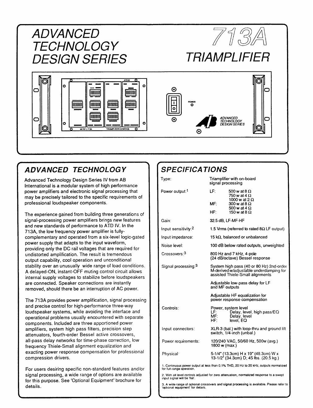
ADVANCED
TECHNOLOGY
DESIGN SERIES

773A i

TRIAMPLIFIER

o
O
a m.
o
E
(D ADVANCED
0 TECHNOLOGY
. DESIGNSEHIES
G
J
r W
ADVANCED TECHNOLOGY SPECIFICATIONS
Advanced Technology Design Series IV from A8 TYPE: Tfiamlnlilierwili} on-board
International is a modular system of high performance Slgna pmcess'
power amplifiers and electronic signal processing that Power output:1 LF; 500w are {2
may be precisely tailored to the specific requirements of 13:52: :19
professional loudspeaker components. Mp: 300w at 8 Q
500 w at 4 Q

The experience gained from building three generations ol HF: 15°" 38 S1
signal-processing power amplifiers brings new Ieatures Gain 32.5 dB, LF-MF-HF

and new standards of performance to ATD IV. In the
713A, the low Irequenoy power amplifier is fully-
complementary and operated from a six-level logic~gated
power supply that adapts to the input waveform,
providing only the DC rail voltages that are required tor
undistorted amplification. The result is tremendous
output capability. cool operation and unconditional
stability over an unusually wide range oi load conditions.
A delayed-ON, instant-OFF muting control circuit allows
internal supply voltages to stabilize belore loudspeakers
are connected. Speaker connections are instantly
removed, should there be an interruption of AC power.

The 713A provides power amplification, signal processing
and precise control for high-performance three-way
loudspeaker systems, while avoiding the intertace and
operational problems usually encountered with separate
components. Included are three apportioned power
amplifiers, system high pass filters, precision step
attenuators, fourth-order Bessel active crossovers,
all-pass delay networks for time-phase correction, low
frequency Thiele-Small alignment equalization and
exacting power response compensation for professional
compression drivers.

For users desiring specific non-standard features and/or
signal processing, a wide range of options are available
tor this purpose. See 'Optional Equipment' brochure for
details.

lnput sensitivity? 1.5 Vrrns (referred to rated an LF output)

Input impedance: is kn. balanced or unbalanced
Noise level: 100 dB below rated outputs, unweighted

800 Hz and 7 kHz, 4-pole
(24 dB/octave) Bessel response

Crossoversz3

Signal processing:3 System high pass (40 or 80 Hz) 2ndcrder
M-derived w/adjustable underdamping tor

assisted ThieIe-Small alignments

Adjustable low-pass delay tor LF
and MF outputs

Adjustable HF equalization lor
power response compensation

Controls: Power, system level
L ' Delay. level, high pass/E0
MF: Delay, level
HF: level, £0

Input connectors: XLR~3 (bal.) with ioop-thru and ground Illt

switch, 1/4-inch (unbal.)

120/240 VAC, 50/60 Hz, 500w (avg)
1800 w (max.)

Power requirements:

Physical 5~1/4'(13.3cm) H x 19' (48.3cm) W x

13-1/2 (34.30m) D; 45 lbs. (20.5 kg.)

1. Continuous power output at less than 0.1% THU. 20 Hz to 20 kHz. outputs normalized
Io! iullranga operation.

2. with all level mntme adjusted lor zero attenuallon, normallled response lo a swept
input signal will be 'ilal'.

a. A Wide range oi optional crossovers and signal processing is available. Please role! to
opllorial equipmenl' to! details.

L J

Page 2

' \
FEATURES AND CONTROLS
HP 50 Hi h ass fit) '90 Hi h frequency EQ control and HF
-5 l 2 4 815 " m -. ° ' = 4" filtgr End in icators (left). The reen on' LED
. ° 5 2 3 associated EQ indicates presenceo HF signal, while
5' E0 control m-\ a s . z . 3.1! the red 'clip' LED shows true clipping.
is at left. These features are repeated for LP
LEVEL /- '7: \-u The high and ME channels. The E0 provides
One of four precision pass filter is 'in' at 40 Hz (t1)_ correchon for driver power response.
level controls used in The E0 is l . .
the 713A is shown enabled, , ' _ A Wide ran e of options 3--
abovej'he switch With 6 dB . are availab e. Shown is '
positions are marked boost. At 12 dB boost centered at
lor insertion loss in right is the 14 kHz beginning at
dB, and sum directly. response. 3.5 kHz tor a popular 2"
12.5 dB attenuation with E0 In ' throat driver, With control :
is shown above. and out. J H; . settings above. 4 4 Hz ii 20k
0 0 m 0 Low and mid frequency delay controls. Delay circuitry is
- "° K'- We W an included in the LF and MF channels to correct for time-phase
O .., 'i. . 5?... 5°. . .. O offsets between the LF-MF-HF loudspeaker components.
r - Switch positions are marked in radians relative to the
[Mllllllllll Uhfinfm .
channels low pass frequency. In the example. 4.04 radians
\ r . have been selected. which corresponds to a physical otlset
mnh- AWN-- Jim's-- mum-«- (all other considerations bein equal) of 10.7 inches at
' gfi iiiiiii'ii'ii'ii fififigfifi gfirir'irir'iri 800 Hz. Combined with ATD Vs lounh-order (24 dB/octave)
m 2 4 B err Bessel crossover lilters, the 713A
W LEVEL LM 9 - ' ' ' ' will deliver virtually seamless. phase
" "" Q coherent performance when used
Pm nn 1" n U" with any wellvdesigned three-way
v w v loudspeaker system. A 'input' switch
0 -~ -~ 0 OUT-I DELAY allows direct comparisons. with and
SVSYEM WFREQJECV MIDFREWENCV NKM FREQUENCY m Without the deIay compensation
0 Warm VRMWLWIER cumin 0
k J
r
SIGNAL FLOW .1 \Sig. Clip
0
/ / HF
High Pass EQ HF Level 150W Output
5 Sig. Clip
Balanced Input / / \ 2 A / HQ)
/ / MF
System High Pass Low Pass Delay MF Level 300W Output
VED: Level (Optional) Sig. Clip
. ,1 \
v-D- \ A /
/ / LF
Unbalanced Input High Pass/E0 Low Pass Delay LF Level 500W Output
k A
r fl
APPEARANCE lllllllllllllllllllUlllllllllllllllllllllllllllllllaa .m-
J is
013
1)
12,0'
ié.
o
. a
u U V7375
"' AB INTERNATIONAL ELECTRONICS, me. (91 ewes-7300 j

i

4}

1830-6 Vernon Street. PO. Box 1105. Roseville, CA 95678

FAX:(916)784-1050