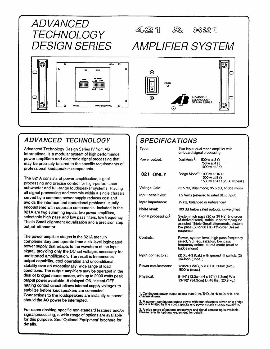
Ab international 421 a brochure

This is the 3 pages manual for ab international 421 a brochure.
Read or download the pdf for free. If you want to contribute, please mail your pdfs to info@audioservicemanuals.com.

Page: 1 / 3
left right
ab international 421 a brochure

Extracted text from ab international 421 a brochure (Ocr-read)


Page 1

ADVANCED
TECHNOLOGY
DESIGN SEFi/ES

43.2% can
AMPLIFIER SYSTEM

o Arm-r o
o .. -.
G
:1 .5"- I-
g 3"
0 ADVANCED
mommy
0 ' DESIGNSERES
D m M36! 0 G
r
ADVANCED TECHNOLOGY SPECIFICATIONS
Advanced Technology Design Series N from AB TYPE: ng International is a modular system of high performance °n oar 59 p' 9
power amplifiers and electronic signal processing that Power output: mat Model: 500 w at 8 {2
may be precisely tailored to the specific requirements of $033230
professional loudspeaker components.
821 ONLY BridgeMode221000wat1BQ

The 821 A consists of power amplification. signal :% 'vv 2:2 2 (2000 w peak)
processing and precise control for high-performance ~ .
subwoofer and lull-range loudspeaker systems. Placing Vflllage Galni 32.5 dB. dual made: 35-5 dB. bndge mode

all signal processing and controls within a single chassis
sewed by a common power supply reduces cost and
avoids the interface and operational problems usually
encountered with separate components. Included in the
821A are two summing inputs. two power amplifiers.
selectable high pass and low pass filters, low frequency
Thiele~Smali alignment equalization and a precision step
output attenuator.

The power amplifier stages in the 821 A are fully
complementary and operate from a six-level logic-gated
power supply that adapts to the waveform of the input
signal. providing only the DC rail voltages necessary for
undistorted amplification. The result is tremendous
output capability. cool operation and unconditional
stability over an exceptionally wide range of load
conditions. The output amplifiers may be operated in the
dual or bridged mono modes. with up to 2000 watts peak
output power available. A delayed-ON. instantOFF
muting control cirwit allows internal supply voltages to
stabilize before loudspeakers are connected.
Connections to the loudspeakers are instantly removed.
should the AC power be interrupted.

For users desiring specific nonstandard features and/or
signal processing. a wide range of options are available
lor this purpose. See 'Optional Equipment brochure for
details.

lnput sensitivity: 1.5 Vrms (referred to rated an output)

lnput impedance: 15 kt), balanced or unbalanced

Noise iovel: too dB below rated outputs. unweighted

Signal processln :3 S stem high pass (20 orao Hz) 2nd-order

9 derived w/adjustable underdamping for

assisted Thiele-Small alignments. system
low pass (50 or 80 Hz) Alhorder Bessel
response

Controls: Power. 5 stem level. high pass frequency

select. V equalization, low pass
lrequency select. output mode (dual or
bridge mono)

(2) XLR-3 (bal.) with ground lilt switch, (2)

input connectors:
. tl4-inch (unbal.)

Power requirements: 120/240 VAC. 50/80 Hz. 500w (avg)
1800 w (max)
Physical: 5-1I4'(13.3cm)H x 19' (48.3w) w x

13-1/2 (34.3w) D: 46 lbs. (20.9 kg.)

Leontinuous erou tetlessthano.1%1iiD.20Hzto 20kHz.one
channel driven!w l9

2. Maxi continuous output power with both channels driven or in pridge
mode ism by line card capacity and power supply storage capability.

3 Awide e of rionel crossovers Ind 5' process is available.
Please refer a: 'opnognal equipment tor detaiigfll m

Page 2

BRIDGE MODE SWITCH 821 ONLY

A switch is provided to operate the amplifier in mono (bridged mode). Refer to the cau-
tion note on this page when using this mode of operation. Bridged load impedances of
less than 4 ohms should not be connected to the amplifier.

BRIDGED MONO OPERATION

1. Set the mode Selector to MONO.

2. Connect a mono input signal to channel one input jack

8. Connect the speaker load to the two red terminals of each channels. Please confirm
the (+) terminal of speaker to channel one and the (-) terminal to channel two.

4. Do not use the black terminals of each channel.

5. Connect the speaker impedance to 4 ohms or above.

6. To adjust level use channel one control and leave channel two level at O.

CAUTION:

DO NOT PARALLEL THE TWO OUTPUTS OF EACH CHANNEL BY CONNECTING
THEM TOGETHER, OR PARALLEL THEM WITH ANY OTHER AMPLIFIER OUTPUT.
NEVER CHANGE A FUSE WITH THE POWER CONNECTED. UNDER NO CIR-
CUMSTANCES SHOULD THE AMPLIFIER BE OPERATED WITH THE COVER
REMOVED. THERE ARE NO USER-SERVICABLE COMPONENTS INSIDE. TO AVOIDA
POTENTIALLY DANGEROUS SHOCK, KEEP THE COVER CLOSED.

A}

LEVEL OUTPUT EO l LP

41) f +41
512481500 semen AIu

D

DUAL

rénv

MODEL 821 SUBWOOFER AMPLIFIER CONTROL