Accuphase P 550 Brochure
This is the 4 pages manual for Accuphase P 550 Brochure.
Read or download the pdf for free.
If you want to contribute, please mail your pdfs to info@audioservicemanuals.com.

Extracted text from Accuphase P 550 Brochure (Ocr-read)
Page 1
$4
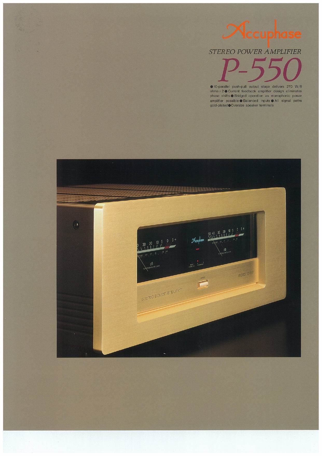
STEREO POWER AMPLIFIER
P550
Ola-pavallel push-pull output stage delivevs 270 W/B
ohms -2.Cunent leedback amplifier design eliminates
phase shvftsOBndged operation as monophonic power
amulmer possibleOEalanced inpulsoml signal paths
gold-platedOOversize speaker terminals
Page 2
If an amplifier is to accurately provide a large
current to its load, that is to say a loudspeaker,
there are two essential prerequisites: the power
supply must be capable of delivering ample
energy, and the high-current output stage must
be designed with low impedance so that its
operation is not adversely affected by the load.
The latter requirement is especially important.
because the impedance of a loudspeaker fluc-
tuates considerably, depending on the fre-
quency of the signal. Only an output stage with
very low impedance will be able to assure
accurate music reproduction under these
demanding conditions.
To fulfill these demands, the P~550 employs
multi-emitter type power transistors specially
developed for high-power audio applications
These advanced devices have wide and flat
frequency response, and their linearity of
forward-current transfer ratio as well as their
switching characteristics are excellent. With
these transistors arranged in a 10-parallel
push-pull configuration. the P-550 achieves an
impressive power output rating of 270 watts
into 8 ohms per Channel. By using bridged
mode. the P-550 can be turned into a mono-
phonic power amplifier with an output of 840
watts into 8 ohms.
Another design highlight of the P-550 is the
current negative feedback" principle. As
opposed to conventional voltage NFB designs,
there is virtually no phase shift in the upper
frequency range, and frequency response does
not change when gain is altered, This new type
of circuit therefore provides ideal amplification
characteristics, combining operation stability
with excellent frequency response. Phase com-
pensation can be kept at a minimum, since
only moderate amounts of NFB are required
This assures outstanding transient response,
and the advantages are clearly audible as
superb sonic realism and extraordinary detail
resolution.
The basic source of energy for an amplifier is
of course the power transformer and the filter-
ing capacitors. Consequently, the sonic end
Powerful and subtle-this amplifier makes music
come alive. Current feedback design puts an end to
phase shifts. Multi-emitter transistors in 10-parallel
push-pull arrangement provide quality power: 270
watts per channel into 8 ohms, or 840 watts into 8
ohms monophonic mode.
result depends to a considerable degree on
how much of a performance margin is built into
the power supply, The P-550 makes absolutely
no compromises in this regard, featuring a
large toroidal power transformer and enormous
filtering capacity. And to maintain absolute
sonic purity, all vital parts where the audio
signal passes, such as the traces on the
printed circuit boards and input and output
terminals are gold-plated.
In the original Accuphase tradition, the P-550
features a champagne gold colored front panel
made from heavy, 15-mm thick extruded alumi-
num with a hand-brushed finish its simple and
uncluttered design gives the amplifier an ele-
gant and sophisticated visual appeal.
Powerful output stage with 10-parallel push-
pull configuration delivers 550 watts into 2
ohms, 420 watts into 4 ohms, or 270 watts
Into 8 ohms per channel
The output stage uses multi-emitter type power
transistors specially developed for audio appli-
cations and rated for a collector power dissipa-
tion of 130 watts and collector current of 15
ampere. These devices offer extraordinarily
wide and flat frequency response, and their
linearity of forward-current transfer ratio as well
as their switching characteristics are outstand-
ing. By arranging these transistors in a 10-
parallel push-pull configuration, the P-550
achieves impressive power output capabilities,
providing a full 550 watts into 2 ohms, 420
watts into 4 ohms, or 270 watts into 8 ohms per
channel.
Figure 1 shows the output circuit configuration
of the P-550. The driver stage employs power
MOS-FETs with negative temperature coeffi-
FIgJ Clrcuil Diagram of the Amplifier Unit (One Channel)
cient. These devices cancel out the positive
temperature coefficient of the bipolar power
transistors, which guarantees perfectly stable
operation under all conditions.
Current feedback circuit topology prevents
phase shifts
When the gain of an amplifying circuit
increases, frequency response, i.e. the ban-
dwidth that can be handled by the amplifier,
becomes more
narrow. To
counter this
effect, a com-
monly em-
ployed tech-
nique called
negative feed- Frequencyfl (in)
back (NFB) mzfrmncymmwlmvolwludbuk
routes part of (Responsu changes when inlnls vanedi
the output signal back to the input. If phase
shift is disregarded, applying a high amount of
NFB results in a circuit with high gain and wide
frequency response, as shown in Figure 2,
Conventional amplifiers employ voltage NFB,
whereby a fraction of the output voltage is
used for the feedback loop. For the lP-550,
Accuphase developed a new type of feedback
circuit topology which uses the signal current
(as) 7
urea...
Trans-impedance pews,
Currant m" llllg
,tmi ad, 9 r amvllllur
I-V 7 4
converter Output
g.
t Input
- Currant NFB m
network
Flgfl Princlplo cl currlnt feedback amplifier
rather than voltage Figure 3 shows the operat-
ing principle of this circuit. At the input point of
the feedback loop, the impedance is kept low
and current detection is performed, A trans-
impedance amplifier then converts the current
into a voltage to a, ,
be supplied to
t h e o u t p u t .
S i n c e t h e
impedance at
th e c u r r e nt
feedback point
(current adder
in Fig. 3) is very an Emmy moonwwllhwrrmtlndwck
'0Y there is (Knows-does rm chewewtengsln hurled)
almost no phase shift. Phase compensation
therefore can be kept at a minimum, resulting
in excellent transient response and superb
sonic transparency.
With this circuit, there is virtually no change in
frequency response when gain is altered. Fig-
ure 4 shows frequency response for different
gain settings of the current feedback amplifier,
The graphs demonstrate that response remains
uniform over a wide range.
utagfi
Frequency -. mu