Accuphase P 400 Brochure
This is the 4 pages manual for Accuphase P 400 Brochure.
Read or download the pdf for free.
If you want to contribute, please mail your pdfs to info@audioservicemanuals.com.

Extracted text from Accuphase P 400 Brochure (Ocr-read)
Page 1
WCCUPLCISG
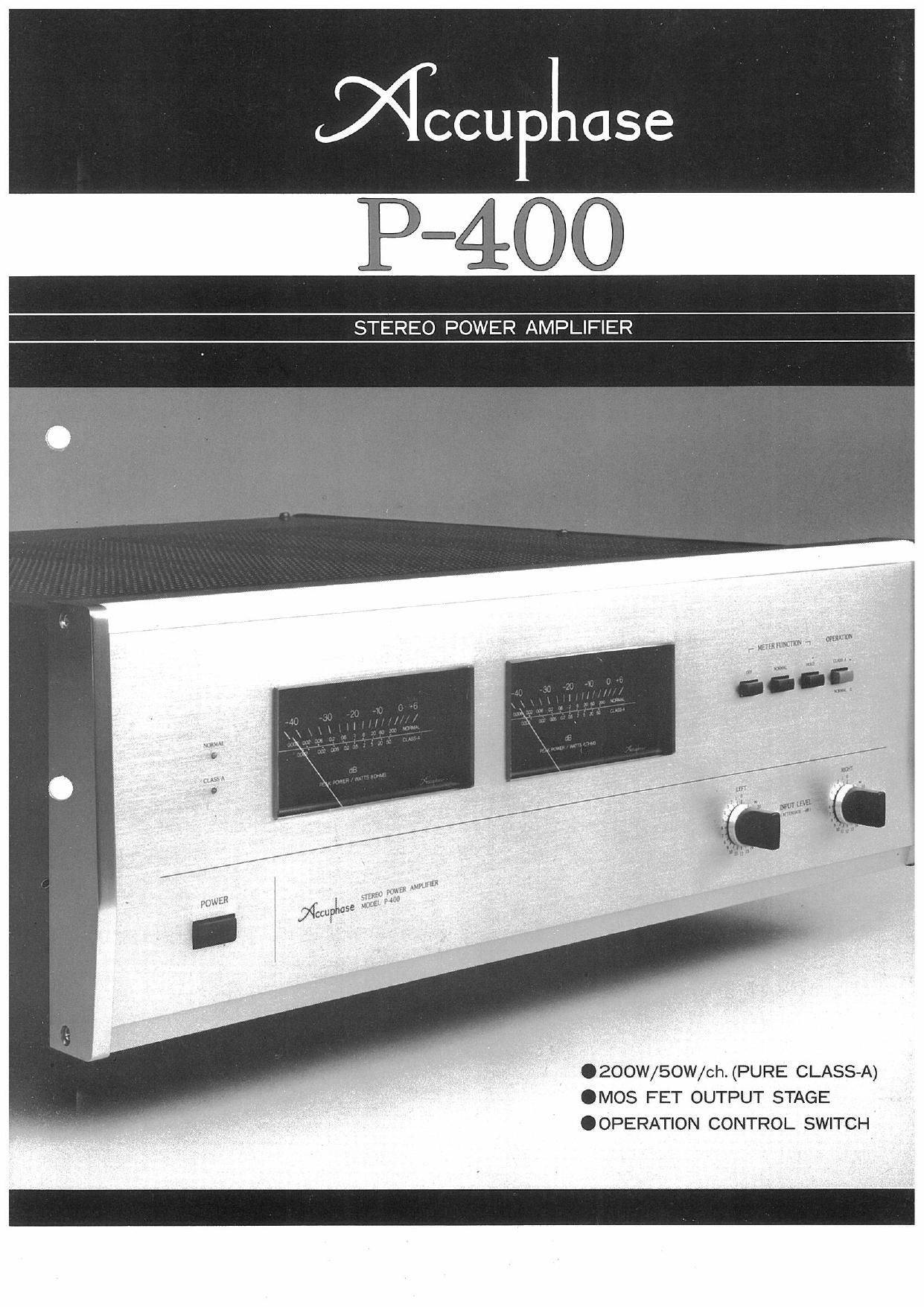
STEREO POWER AMPLIFIER
mm
- Minkam. 1 ma
1 1 H
Hm : )4": 01(st
.200W/50W/ch. (PURE CLASS-A)
.MOS FET OUTPUT STAGE
.OPERATION CONTROL SWITCH
Page 2
The Accuphase P7400 is a highest grade stereo power amplifier
which forms a perfect combination with the highly regarded Accuphase
C7240 Control Center. The P-4OO employs MOS FETs (Metal70xide
Semiconductor FETsI, considered the most promising active device for
power amplifier applications, in a triple push-pull output stage that
delivers the high power of 200 watts per channel.
One of the main features of the P-AOO is that the advantages of
minimum distortion offered by pure Class-A amplifier operation can be
enjoyed by switch control. Class-A operation offers a higher degree of
perfection in amplification characteristics, especially in the high fre-
quency range. In addition, the use of MOS FETs in the P-4OO e'nsures a
complete absence of notching distortion.
Although output power falls to 50 watts per channel during Class-A
operation, it is adequate to drive medium efficiency speakers, rated
around QOdB/W/m, with ample sound pressure.
The P400 employs the "Accuphase Original" complementary-
symmetry push-pull, DC Servo Controlled amplifier circuitry. It is
designed to deliver highest grade sound reproduction with its pure
monophonic type construction which features completely separated,
independent power supplies for its left and right channels.
I PURE CLASS-A OPERATION
Pure Class-A amplifier operation is offered by the P-400 to minimize
distortion and achieve further perfection of sonnd reproduction quality
in response to the constant search of hi-fi enthusiasts for better sound.
Another reason is the fact that conventional power amplifiers which
ordinarily employ Class-B or Class-AB amplification have about reached
their respective theoretical performance limitations.
When the P-4OO is switched to Class-A mode, the operating slopes of
its push-pull devices perfectly overlap each other as they should in pure
Class-A operation. This means that operational and thermal stability is
maintained at all times because constant energy flows from its power
supplies to the amplifying devices.
This improved stability is another big advantage of pure CIass»A
operation, since widely fluctuating signals cause no change of current
and thermal conditions in the amplifying devices as they do in Class-B
or AB operation, with their attendant distortion problems. Therefore,
the advantages of pure Class-A operation, as applied in the P-AOO with
its perfectly matched operational MOS FETs, ensure the highest state
of the art in sound reproduction performance, and far omweigh the
disadvantage of reduced output power for ordinary listening.
Switching to ClassAA mode is achieved electronically, not mechan-
ically, with a bias circuit selecting system. On and On in the
amplifier block diagram of Figure 1 shows how this is done. 0 is a
transistor which activates the bias resistor "VR" ON or OFF. 013 is an
Opto»CoupIer which controls 0. It includes a photo transistor and a
light emitting diode. O, 3 is inactive during NORMAL mode, so Q.2
goes ON to short the bias resistor VR out of the circuit for the normal.
high power operation of the driver and final output stages.
When the OPERATION switch is set to CLASS-A mode, current
fl a
Fig.1 MOS FETs' SYMMETRICAL PUSH-PULL DC POWER AMP.
flows through the Light Emitting Diode (LED) and activates the Photo
Transistor O. This turns 0 OFF and activates resistor VR of the
bias circuit, which causes Class-A amplification bias current to flow
through the drive and final output stages. It also simultaneOUsly lowers
the B voltage applied to the output MOS FET devices for Class-A
operation. Transistors C1 to O9 operate at all times as CIass»A
amplifiers. Very stable operation is achieved in this manner since
operational mode switching is accomplished without moving the signal
path circuit around excessively.
The OPERATION switch on the front panel controls the selection
of Normal or Class-A operation, and the LED lamps will be coinci-
dently switched over to indicate operation mode.
2 mos FET OUTPUT STAGE
The output stage employs MOS FET devices, which are regarded as
most ideal for power amplifier applications, in a triple pushvpuli
circuitry. MOS FETs possess many characteristics that make them more
suitable than bipolar or SIT (VvFET) transistors for this function. They
significantly improve high frequency performance characteristics since
they do not cause notching distortion. They also effectively reduce
harmful transient intermodulation distortion because of their 0
frequency range characteristics. In addition, MOS FETs assure
proved overall performance since they are high gain, voltage controlled
devices which fact simplifies ClassrA amplifier design for the preceding
driver amplifier stages.
3 SERVO CONTROLLED DC AMPLIFIER
The complete elimination of input capacitors and large capacitors in
the NF loop has made the P-400 a true DC amplifier that assures
minimum coloration of sound. A DC Servo Control system was adopted
to achieve this, and eliminate all DC drift at the output and prevent
passage ol DC current.0therwise, any DC leakage from the preamplifier
would be amplified in the final stage and pass on to cause damage to
the speakers.
The two integrated circuits lleI in Figure 1 make up the DC Servo
Control circuitry. it detects and amplifies any DC voltage that may
appear at the output. It uses this energy to control the gate voltage oi
Cllb. the input dilferential ampliiier circuit of the Servo Control
circuitry. For example, if a DC + current should appear at the output, it
womd cause the bias voltage of oil: also to turn positive, which in turn
causes a reduction in the DC potential at the output. This process
repeats itself until DC output potential is '0, which is maintained by
lhe Servo Control system at all times.
4 COMPLEMENTARY-SYMMETRY PUSH-PULL
AMPLIFIERS IN EVERY STAGE
Every amplifier stage employs a complementary-symmetry push»
pull circuitry, which is an "Accuphase Original." This circuit has
superior inherent characteristics and requires minimum application of
negative feedback (NFB), particularly because of its outstanding
linearity. This accounts for its extremely low distortion ratio and high
amplification stability. This also prevents TIM (transient intermodula»
tion) distortion and ensures a big improvement in the quality of sound
reproduction.
Distortion data are shown in the last page, and Fig. 2 shows the IM
Distortion data under new IHF Standard Methods of Measurement
defined in 1978.
When plural signals closed each other in frequency cause nonlinear
distortion, as well as harmonic distortion of each original signals, a third
signal of difference in frequency between each signals appears and
deteriorates the reproduction sound. This is the process of the IM
Distortion stated in the new lHF. This distortion is occasionally called
as BEAT DISTORTION. Even if original signals are out of the audible
range, such a distorted third signal comes to appear in the audible range
and it results in a deterioration of sound quality. This became a great
issue recently. This kind of IM Distortion is apart from the former
lntermodulation Distortion which is measured with the frequencies of
SOHZ or GOHZ vs 7.000Hz and is called as "SMPTEJM".
Refer to Fig.2. It shows the distortion spectrum of the P-400 which