Accuphase P 360 Brochure
This is the 6 pages manual for Accuphase P 360 Brochure.
Read or download the pdf for free.
If you want to contribute, please mail your pdfs to info@audioservicemanuals.com.

Extracted text from Accuphase P 360 Brochure (Ocr-read)
Page 1
mccuPLase
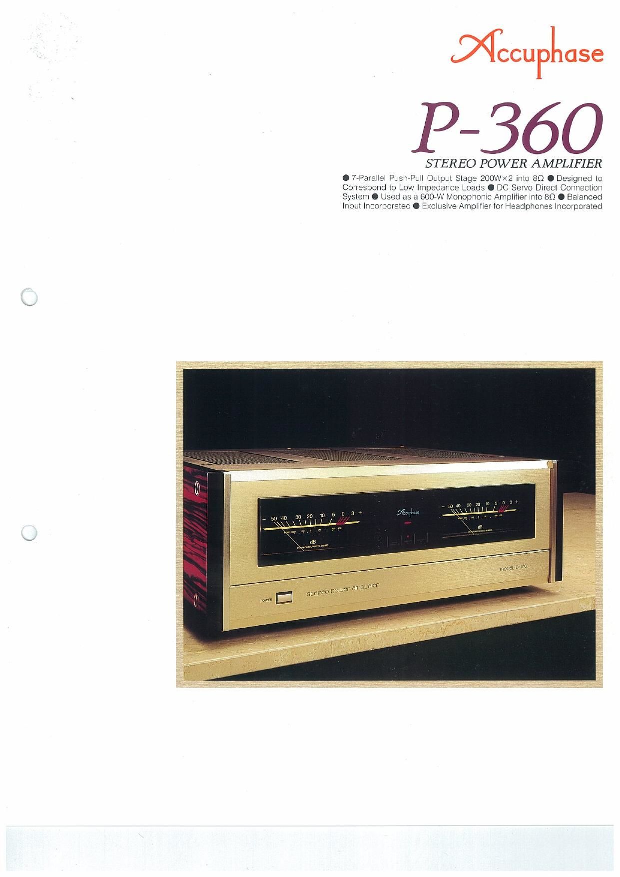
P660
STEREO POWER AMPLIFIER
O 7-Parallel PusflPuH Output Stage 200W><2 into 80 0 Designed to
Correspond to Low Impedance Loads 0 DC Servo Dwrect Connection
System 0 Used as a GOO-W Monophonic Amphfier into 80 O Baanced
Input Incorporated 0 Exclusive Amplifier for Headphones Incorporated
Page 2
The power amplifier is. in a way. the driving unit
or power source for the speakers. Therefore,
power amplifiers are required to faithfully drive
the speakers with great stability without being
affected by the rapid fluctuation of the speakers'
impedance All of Accuphase's power am-
plifiers are designed to comply with such re-
quirements The P-360 has been developed to
meet such stringent prerequisites incorporating
the most advanced circuit topology and compo-
nents available today,
The output stage of the P-360 is equipped with
7 powerful parallel push-pull transistor pairs,
that can deliver a maximum current of210A for a
period of l/f.000 sec as well as a powerful
toroidal power transformer with a capacity of
1.000VA and a huge capacity power supply that
is made up of two 40.000uF electrolytic conden-
sers, The P4360 can. therefore deliver a stable
and ample output of 400W per channel into
20hm loads, 300W per channel into 40hm
loads. and 200W per channel into 8 Ohm loads.
When bridged. the P»360 can work as a fully
balanced monophonic power amplifier that can
deliver 800W into 4 Ohm loads and 600W into
8 Ohm loads.
With the aim to achieve the utmost in perform-
ance. the front stage now incorporates an ex-
travagant cichit configuration. which consists of
a high performance class-A cascode circuit and
a MOS-FET cascode push-pull circuit. This cir-
cuit configuration is considered today to be the
most ideal circuit topology for such an amplifier
stage.
All of our products. including tuners. incorpo-
rate Accuphases exclusive balanced signal
transmission system. that features a direct input
into the differential amplifier Circuit at the input
stage. This is ideal. because it does not require a
signal-converting amplifier. which may impair
audio quality.
An additional feature of the P-SESO is an inde-
pendent amplifier exclusively dedicated to
headphone operation. This makes it possible to
monitor and enjoy the highest quality music
reproduction through headphones.
The P-360 is also equipped with such useful
functions as front input terminals. which can be
used for connecting peripheral equipment. and
a speaker system selector that enables the
selection of two pairs of speakers. We are con»
fident that our latest innovation. the P-SSO. has
successfully pursued the goal of obtaining the
utmost performance as a power amplifier.
7 Powerful Parallel Push-Pull Transistor Dri-
ven Output stage Offers Ample Power Reser-
ves: 200 Watts per Channel into 8 Ohms, 400
Watts per Channel Into 2 Ohms, and Capablli-
ty to Drive Even 1 Ohm Loads
The impedance of a speaker varies widely de-
pending on frequencies reproduced. Even if the
impedance of a speaker system is rated at
8 Ohms. the actual impedance sometimes goes
down to nearly 2 Ohms at certain frequencies.
Therefore. the output impedance of a power
Incorporating FET Input Circuitry,
All-Stage Push-Pull Circuitry, DC Servo System that
Directly Connects All Audio Signal Circuits, and
High Capacity Toroidal Transformer and
the 7-Parallel Push-Pull Output Stage that Can
Produce a Stereophonic Output of 200W per Channel and
a Monophonic Output of 600W into 89.
amplifier should be as low as possible to drive all
kinds of speakers without any strain. The em-
ployment of an NFB (negative feedback) can
seemingly lower the output impedance. but it
does not always deliver high quality electric
current. Therefore. an output circuit. that can
truly deliver a large electric current is required.
[
Inf-I
I. I. f
r~vvv vy '
As shown in the Fig. 1. the P-BBO utilizes an
output transistor capable of a large electric cur-
rent drain in a 7-parallel push-pull configuration.
which enables the delivery of an electric current
as high as 21 0A for 1ms (which is equivalent to a
1kHz musical signal for 1/1.000 sec). This actu-
ally equals as much electric power as 44kW into
a 1 Ohm load. which guarantees a truly pheno-
menal driveabilily.
High Power Supply Circuit Conststlng of
High Efficient. Large Sized Toroidal Trans-
former and Large Filters Capacitors
The basis of music reproduction is the faithful
reproduction of low frequency sounds. To satis-
factorily reproduce a substantial low frequency
sound, it largely depends on the electric power
supply capability of the power supply circuit To
realize this. such prerequisites must be met: the
power transformer
should have a large
electric power capac-
ity and the tiller con-
denser should have a
high energy holding
capability, Thanks to
its highly efficient.
large size. 1kVA toroi-
dal transformer and
Loads As Low As an Impedance of 29 Can be Perfectly Driven.
two filter condensers
with a capacitance
value of 40.000uF. the
P-SBO obtains a flat
output voltage to Gov-
er the entire frequen-
cy range from 20Hz to
20.000Hz.
\
t
Class-A Cascade Push-Pull and MOS-Fig
Cascade Push-Pull Driver Stage Improves
High Frequency Characteristics and Her:
monlc Distortion at Low Output Level
The driver stage employs Accuphase's original
MOS-FET and casccde push-pull circuitry. Gen-
erally. power transistors to be used in audio
power amplifiers need to amplify a wide dy-
namic range of audio frequencies from minute
signal levelstohigh amplitudelevelswnhlineari-
ty and without distortion. A push-pull circuitry is
usually employed for a power amplifier stage.
which consists of NPN- and PNPvtype transis-
tors. thus inevitably causing so-called switching
distortion. when signals switch from one transis«
tor to the other. Accu- . >
phases amplifiers em- ' '
ploy MOS-FET's in the
driver stage. which is
further connected in a
cascode push~pull con-
figuration. This remark-
ably improves the per-
formance characteris-
tics at low signal output levels.
Moreover. the output stage employs a bipol"
transistor with a positive temperature coef-
ficient, while the driver stage employs MOS»
FET's With a negative temperature coefficient.
thus cancelling each other out to achieve a
highly stable power amplification. Also employ-
ed in the ore-driver stage is a classAA cascode
push-pull Circuitry. which additionally contri-
butes to the stability of the MOS-FETs function.
-rNPur
+INPUY
Fig. 1 Circuit diagram at P-360