Accuphase P 1000 Brochure
This is the 4 pages manual for Accuphase P 1000 Brochure.
Read or download the pdf for free.
If you want to contribute, please mail your pdfs to info@audioservicemanuals.com.

Extracted text from Accuphase P 1000 Brochure (Ocr-read)
Page 2
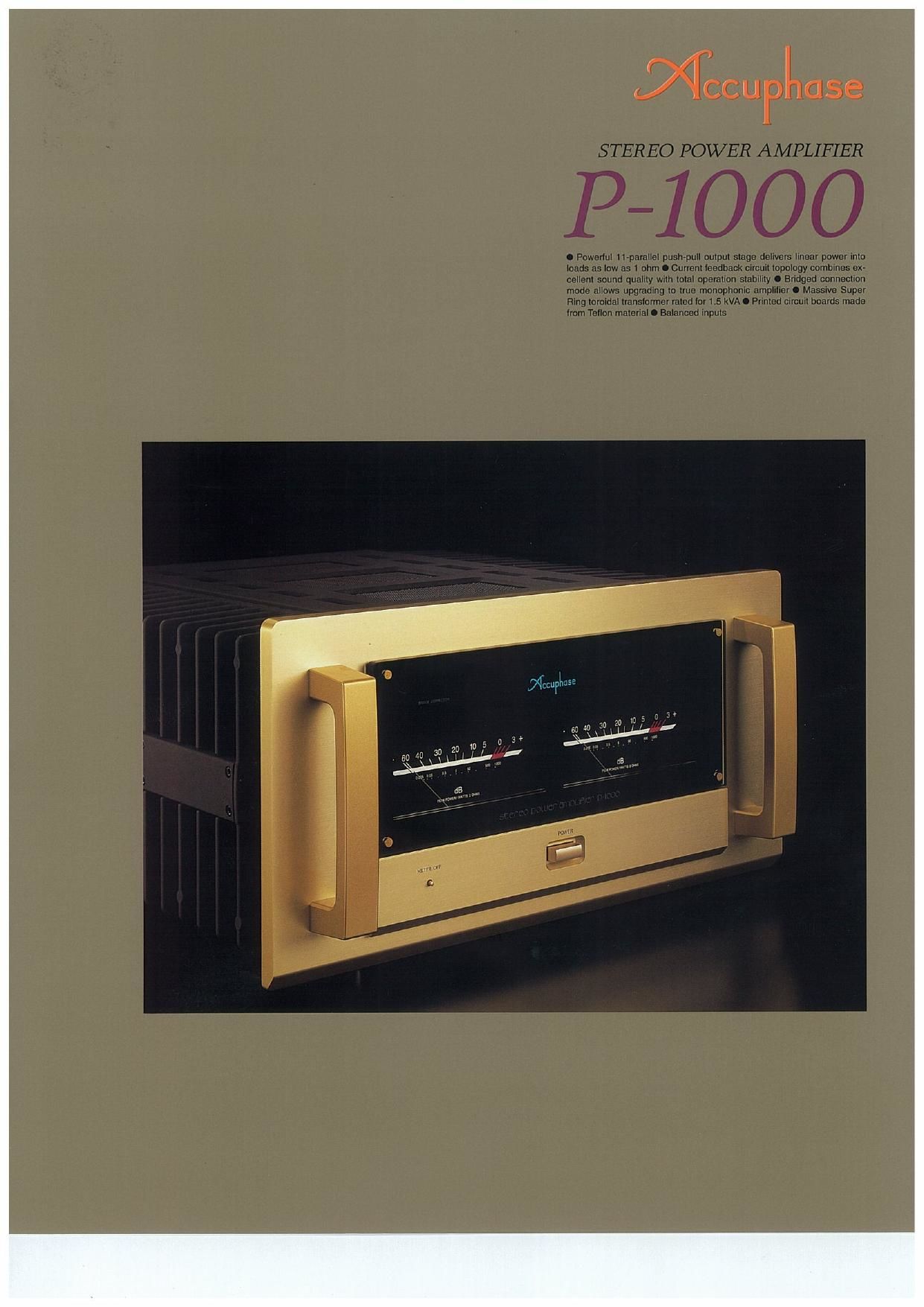
The Accuphase monophonic power amplifier
M-2000 and the pure class A stereo power
amplifier A-SOV have been hailed as stunning
achievements, both for their outstanding technical
performance and impeccable sound quality. While
these two models employ somewhat different
circuit topology. their underlying philosophy is the
same: to provide extremely low output impedance
(Note 1), and to be capable of supplying a constant
drive voltage at all times (Note 2).
The P-1000 achieves these same goals with even
more sophisticated technology. It is a stereo power
amplifierthat attains yet anotherdimension of sonic
excellence It is penect for the new generation of
ultra high quality program sources such as SACD
and DVD-Audio. Regarding frequency response
(0.5 Hz - 160 kHz), SIN ratio, and all other perfor-
mance aspects, the P~1000 is fully ready for the
requirements of the future.
The output uses 11 pairs of high-power transistors
in each channel, arranged in a parallel push-pull
configuration. These devices are mounted to mas-
sive heat sinks that provide efficient dissipation of
thermal energy. Power linearity is maintained down
to ultra low impedance loads of 1 ohm. By using
the P-1000 in bridged mode, the user can create a
mono amplifier with even more impressive power
reserves. The power supply features a highly effi-
cient "Super Fling" toroidal transformer and large
filtering capacitors.
Current feedback topology combines total opera-
tion stability with excellent frequency response,
while requiring only minimal amounts of negative
feedback. Accuphase research has shown that the
material used for printed circuit boards has a deci-
sive influence not only on electrical characteristics
but also on the sonic end result. The P-1000 uses
a Teflon material with extremely low dielectric con
stant and low loss, resulting in more transparent
sound.
The P-1000 is a power amplifier that already im-
presses by its sheer physical presence. But more
importantly, it brings music to life with a dynamic
impact and richness of detail that must be heard
to be believed.
/ '\
Note 1 The reasoning for low amplifier out-
put impedance
The load of a poweramplifier, namely the loud- i
speaker, generates a counterelectromotive
force that can flow back into the amplifier via
the NF loop. This phenomenon is influenced
by fluctuations in speaker impedance, and in-
terferes with the drive performance of the
amplifier. The output impedance of a power
amplifier should therefore be made as low as
possible by using output devices with high cur-
rent capability. This absorbs the
counterelectromotive force generated by the
voice coil and prevents the occurrence of
intermodulation distortion.
Note 2 The constant drive voltage principle
Even in the presence of a load with wildly fluc- '
tuating impedance. the ideal power amplifier
should deliver a constant voltage signal to the
load. When the supplied voltage remains con- i
stant for any impedance. output power will be
inversely proportional to the impedance of the
load. A conventional amplifier can be easily
made to operate in this way down to a load
impedance of about 4 ohms At 1 ohm. how-
ever, eight times the output of an B-ohm load
is called for. which can only be sustained by
an extremely well designed and capable out-
put stage and a highly robust and powerful
power supply section.To build such an ampli-
fier is a task that requires not only consider-
able experience and resources but also a thor-
»\ ough rethinking of basic principles,
Modular power units In 11-parallel push-pull
configuratlon deliver linear output: 1,000 watts]
ch. Into 1 ohm, 500 watts/ch. into 2 ohms, 250
watts/she into 4 ohms. 125 watts/ch. into 3 ohms
The output stage uses high-power transistors with
a rated collector dissipation of 130 watts and col-
lector current of 15 A. These devices have excel~
lent frequency response. current amplification lin-
earity, and switching characteristics. The transis-
tors are arranged in an 11-parallel push-pull con
figuration (Figure 1) for ultra-low impedance and
are mounted on a massive heat sink made from
diecast aluminum. This assures effective heat dis-
An experience in excellence - Witness 3 stereo power amplifier capable of deliver-
ing 1000 watts into l-ohm loads. Constant drive voltage principle ensures total
speaker control. High-performance power transistors connected in an 11-parallel
push-pull configuration deliver linear power even into extremely low impedances.
Current feedback topology guarantees stable operation up to ultra high frequen-
cies. Performance specs fully cover the requirements of new-generation program
sources such as SACD and DVD-Audio.
sipation and allows the amplilier to effortlessly
handle very low impedances. Power linearity is
maintained down
to loads as low as
1 ohm, which
demonstrates the
impressive capa- an
bilities of this am-
plifier.
Figure 2 shows
the output/volt-
age characteris-
tics at various
load impedances.
It can be seen
that output volt~
age remains
nearly constant 0
regardless of
load. which FluurlZ Load Impedance vlreutputpowar
means "131 OUi' (output VDIIIIU/autput currlnt)
put current increases linearly,
in
a
Output current (A) -.
In at on w an
output Voltage iv) ->
Current feedback circuit topology prevents
phase shifts
The P-1000 employs the so-called current feed
back principle. Figure 3 shows the operating prin-
Vinpul > \ Currant adder
Butter _ w 93pm
Tmns~lmpedance
. mpui amplifier
Buffer
I Current NFB I
network
Figure 3 Prlnclple or current feedback ampllflor
ciple of this circuit. At the sensing point of the feed-
back loop, the impedance is kept low and current
detection is performed. An impedance-
- leur
quur 0,
nzwm
-Ei
Figure 1 Circuit diagram of amplifier section (one channel)
converting amplifier then converts the
current into a voltage to be used as the
feedback signal. Since the impedance
at the current feedback point (current
v97 adder in Figure 3) is very low, there is
almost no phase shift. Phase compen-
sation can be kept to a minimum, re-
sulting in excellent transient response
and superb sonic transparency. Figure
4 shows frequency response for differ-
ent gain settings of the current feedback
outrun
(as)
Gm a
Flguh : rim-m nlpunuwtm cumt inch-er
rim l-mlms mm mom-m Wnchnngiu)