Accuphase E 303 Brochure
This is the 4 pages manual for Accuphase E 303 Brochure.
Read or download the pdf for free.
If you want to contribute, please mail your pdfs to info@audioservicemanuals.com.

Extracted text from Accuphase E 303 Brochure (Ocr-read)
Page 2
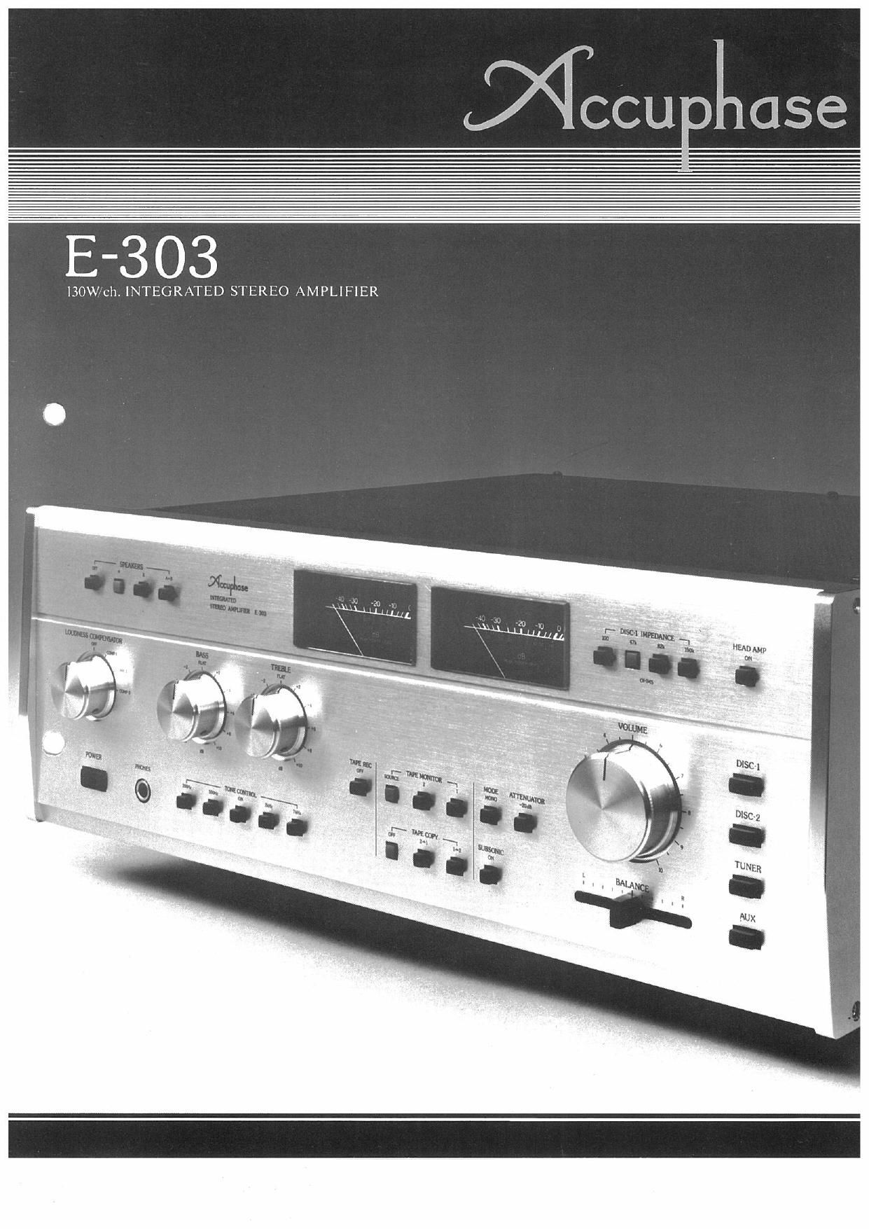
The Accuphase E7303 is a integrated stereo amplifier that is ideal for
those audio enthusiasts and music lovers who have felt that while they
always desired highest quality reproduction, separate amplifiers seemed
too complicated and required too much space . , "
The E7303 is ideal because it incorporates all the capabilities of
separate amplifiers in one single unit, and is one of the most powerful
integrated amplifiers today. Power output is 130 watts per channel (20
to 20,000 Hz into 8 ohms) with distortion less than 002%.
It also has a built-in Head Amplifier to which low-output, high
quality Moving-coil cartridges can be directly connected.
The extravagant circuitry consists of Accuphase's original" Come
plementaryrSymmetry PushrPull driven amplifier circuits in every stage,
which have effectively reduced harmful Transient Intermodulation
Distortion (TIM).
One of the main features is the use of MOS FET (MetalAOxide
Semiconductor FET) devices in a parallel push»pull power output stage,
MOS FET is a new, ideal power amplification device. It has given birth
to an amplifier which approaches the classVA operation ideal of amp
designers much closer than was ever possible before with bipolar
transistors,
DC amplifier units are used throughout which have eliminated the
need for large capacity capacitors in the Negative Feedback loop. This
has reduced sound coloration to a minimum. The high-level amplifier
section which contains the tone control circuit is a servo controlled DC
AMP. It permits the circuit to operate as a DC amplifier, even when
the tone control is on, so there is no noise when the tone control is
switched on or off.
This amplifier also features ICL design. All unit amps require no
input capacitors and the elimination of a large capacity input capacitor
at the head amplifier has contributed greatly to sound quality
improvement.
Enjoy the glorious world of music with the E303 which is the result
of our many years of amplifier design experience, and our most recent
objective to produce an outstanding integrated amplifier with the same
high quality performance of high quality separate amplifiers.
I 130W/CHANNEL REALIZED WITH MOS FETs
"What is the ideal power output device?"
This question has long been a subject of debate, but ever since the
potentialities of the MOS FET were revealed at the Audio Engineering
Society (USA), in May, 1976, it became apparent, without question,
that this active device held the most promise for the future. However,
the birth of high power MOS FETs took a long time due to technical
production difficulties. It was finally realized here in Japan ahead of
the world. As a result, audio amplifier performance will most likely
enter a new era.
The E-303 is the first integrated amplifier which employs these
powerful MOS FETs. Four of them are used in a parallel push-pull
output stage, and account for the high output power of 130 watts per
channel.
Since the MOS FET has characteristics which make it easier to use
than bipolar transistors or V-FETs, and also because there is no
notching distortion during high frequency transmission, there is a
significant improvement in treble response. Moreover, its high fre-
quency characteristics are excellent and effectively confines harmful
TIM to a minimum.
It does not create notching distortion because of its extremely high
input impedance, and also because it is voltage controlled, and requires
very little power from the previous stage This makes it possible and
easier to utilize a classrA driver amplifier stage with the result that
superior characteristics, closer to the ideal classrA operation, can be
realized than with bipolar transistors.
Moreover, the MOS FET has a very high gain equivalent to two or
three stages of directly coupled Darlington Pair amplifier circuits using
bipolar transistors, This permits reducing the number of stages and
presents the advantage of superior performance
Figure 1 shows the power amplifier section of the E303. Only one
Darlington Pair high gain stage is employed between the input
differential amp stage and parallel push-pull output. The signal path is
very clear cut. The transistors that drive the MOS FETs are employed in
a Complementary-Symmetry classA application and need only to
ensure low output impedance of the driver stage.
The bipolar transistor may seem to be full of faults from the above
explanation, but it was presented only as a matter of comparis n.
Nevertheless, a high perfection amplifier can be made even
bipolar transistors when it is wel|~designed. U
EVERY STAGE IS COMPLEMENTARY-SYMMETRY
PUSH-PULL AMPLIFIER
Every stage from the Head Amplifier input to the MOS FET output
is a complementarysymmetry push~pul| amplifier circuit. Although it
uses almost twice the number of components compared to ordinary
circuitst its inherent characteristics, without negative feedback applica-
tion, and especially its linearity are very superior. Thus, it is a big
advantage that it requires only a small amount of negative feedback to
maintain lhedisiortion low,
TIM which is harmful to sound quality, is one type of distortion
which has been effectively reduced because of this circuit, We have
focused our attention on the many advantages of the complementary-
symmetry push-pull circuit, and have adopted it completely in all our
amplifiers from the very first P7300 and 0200. This circuit (which is
increasingly gaining favor) can well be called an Accuphase "original,
3 DC UNIT AMPS
All unit amps are DC types and DC amplifier design was adopted
throughout. Large capacity, direct current blocking capacitors in the
NF loops were removed and sound coloration was eliminated.
This required complete control of DC drift which was geneu
recognized as being very difficult in the highrlevel amplifier section
contains tone control elements, and where its switches and volume
control change the values of NF elements.
However, new Servo Control method which completely prevents
oc drift was developed and adopted, It allows DC amplifier operation
even when the tone control circuit is on.
The Servo Control method is shown in Figure 2. DC drift detected
fl RIPPLE 7, o
% +ssv
ia- "51v
N
oz) 4%
a i
INPUT '
~76} a) 7% meourput
f l
0W (K r) l
g to t
. #75"
f i
55v
9
T I
gem-i
to-
.m-
K l o+|§V
mm. Ti ' } vourpur
z i Q
f
Dc SERVO AMP, o~
(FIG. ll MOS FETs' SYMMETRICAL PUSH-PULL POWER AMP.
lFIG.2) SERVO CONTROLLED HIGH-LEVEL AMP.