Accuphase E 211 Brochure
This is the 4 pages manual for Accuphase E 211 Brochure.
Read or download the pdf for free.
If you want to contribute, please mail your pdfs to info@audioservicemanuals.com.

Extracted text from Accuphase E 211 Brochure (Ocr-read)
Page 1
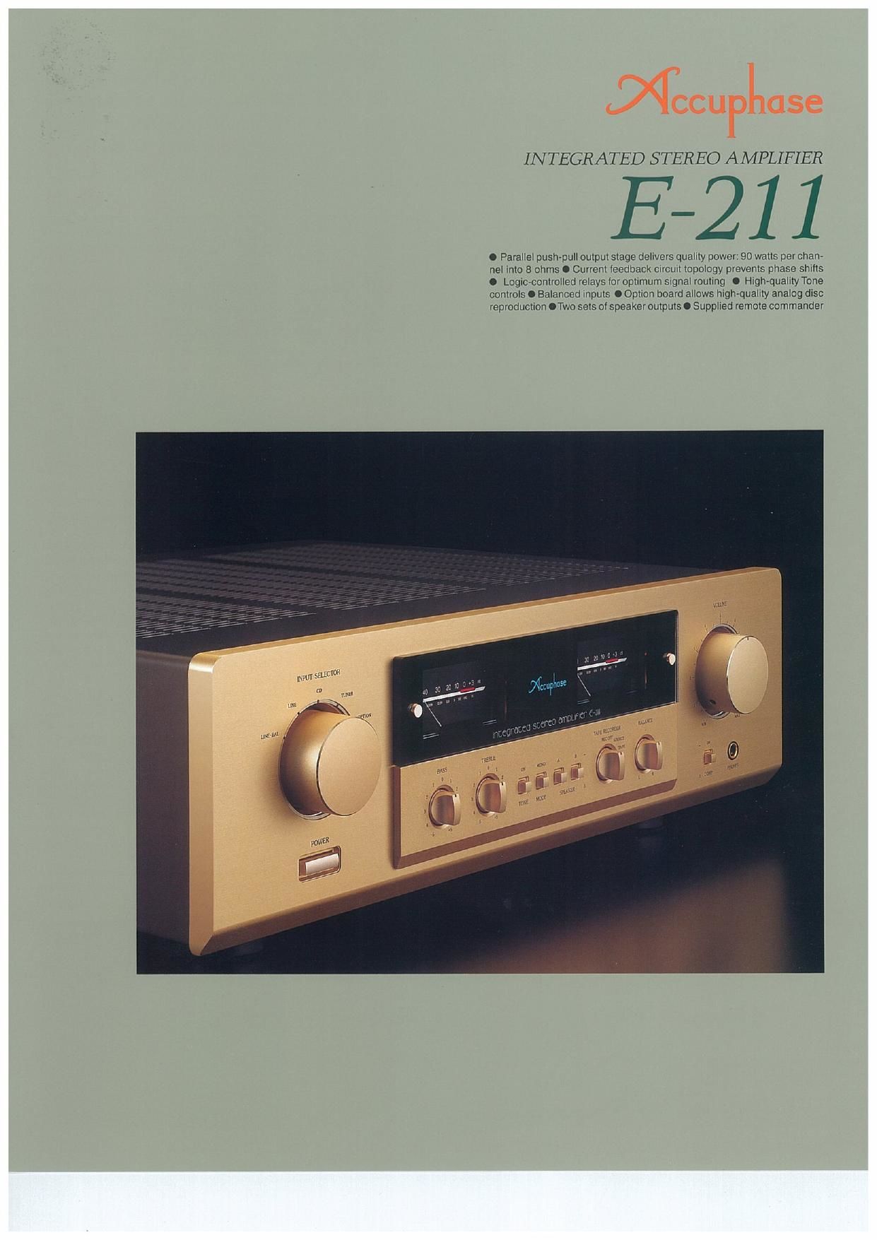
INTEGRATED STEREO AMPLIFIER
E-211
0 Parallel pushpull output stage delivers quality power 90 watts per chan~
nel into 8 ohms 0 Current leedback Clrcull topology prevents phase shilts
O Logiorcontrolled telays lor optimum signal roulmg I High-quality Tone
controls 0 Balanced mom: I Option board allows high~quallty analog disc
reproductton OTwo sets at speaker outputs O Supplied remote commandet
Page 2
The E-211 is a further refined successor
model to the highly acclaimed E-210. it adds
power meters, tone controls and other fea-
tures while retaining the simple design and
impeccable sound that is made possible by
Accuphase technology developed for our cel-
ebrated separate components. While surpris-
ingly affordable, the E211 delivers perfor-
mance that far surpasses the realm of con-
ventional products in this class.
in an integrated amplifier, overall gain is very
high. Consequently, even minute interference
or noise at the input side can severely degrade
sound quality. To prevent this, the E-211 keeps
the line amplifier and power amplifier sections
entirely separate, both regarding mechanical
construction and electrical circuitry.This keeps
the signal path simple, while totally elimina-
ting the possibility of mutual interference be-
tween the low-level signal switching sections
and the power amplification circuitry, The re-
sult is a clear improvement in sonic purity. An-
other significant advantage is the current feed-
back topology developed by Accuphase. It
virtually eliminates phase shifts in the upper
frequency range and assures uniform fre-
quency response which does not change with
gain.Total operation stability is combined with
excellent frequency response. Thanks to this
principle, phase compensation can be kept
at a minimum, and high amounts of negative
feedback with their associated disadvantages
are no longer required.
The output stage employs a parallel push-pull
configuration of multi-emitter type power tran-
sistors designed for highcurrent audio appli-
cations. The drive stage uses MOS-FET de-
vices which have negative temperature char-
acteristics. This means that there is no dan-
ger of thermal runaway" as exists with bipo-
lar transistors, assuring stable operation un-
der all circumstances.
Sheer musical exhilaration - A new integrated amplifier with cur-
rent feedback topology and a full complement of valuable features.
The drive stage uses power MOS-FETs, and the parallel push-
pull output stage employs high-current power transistors deliver-
ing 90 watts/channel of quality power into 8 ohms. Option board
allows analog disc playback with impeccable quality.
In the standard configuration, the E-211 pro-
vides five inputs including a balanced input.
An additional line input can be added as an
option. Another attractive option is the analog
disc input board, which provides high-quality
phono playback. This will be welcomed by
audiophiles with a treasured collection of ana-
log records.
Tone controls configured as summing active
filter circuits provide flexibility without diluting
the purity of the music signal, A loudness com-
pensator allows precise adjustment and re»
stores proper sonic balance at low listening
levels.
Parallel push-pull power unit delivers 115
watts/ch into 4 ohms, 105 watts/ch into 6
ohms, and 90 watts/ch into 8 ohms
The transistors used in the output stage are
quality devices designed for audio applica-
Power transistors
tions, with high collector dissipation, optimum
high-frequency characteristics. and superior
resistance to current breakdown. The power
transistors are devices designed for high-
power audio applications. with outstanding lin-
earity and switching performance character:
istics. By mounting these transistors to a large
efficient heat sink and connecting them in par-
allel, the E-211 achieves ample power output
capabilities, providing 115 watts into 4 ohms,
105 watts into 6 ohms, or 90 watts into 3 ohms
per channel.
The driver stage uses MOS~FET devices with
+52
0 output
Figure 1 Power amplifier assembly (one channel)
on
732
negative temperature characteristics, which
cancels out the thermal characteristics of the
power transistors and guarantees perfectly
stable operation.
Current feedback circuit topology prevents
phase shifts
Conventional amplifiers employ voltage NFB,
whereby the output voltage is used for the
feedback loop. In the E-211, however, the sig-
Cummi mm
Input WWW Oulput
ewe: Tnnsdmpodlmo
amiiiiu
Currant Nra
network
Figure 2 Principle of current feedback amplifier
nal current rather than the voltage is used for
feedback. Figure 2 shows the operating prin-
ciple of this circuit. At the sensing point of the
feedback loop, the impedance is kept low and
current detection is performed An impedance-
converting amplifier then converts the current
into a voltage to be used as the feedback sig-
nal. Since the impedance at the current feed-
back point (current adder in Figure 2) is very
low, there is almost no phase shift. Phase
compensation can be kept to a minimum, re-
sulting in excellent transient response and
superb sonic transparency. Figure 3 shows
frequency re-
sponse for dif-
ferent gain set-
tings of the
current feed-
back amplifier.
The graphs
demonstrate __
that response mammmmgrgk
remains uni-
form over a wide range.
Highly reliable logic-controlled relays
Long signal paths for functions such as input
switching and tape monitoring tend to degrade
high-frequency response and impair imaging.
The hermetically sealed relays are high-qual-
ity types developed specifically for demand-
ing communication applicationsThe contacts