Accuphase C 7 Brochure
This is the 2 pages manual for Accuphase C 7 Brochure.
Read or download the pdf for free.
If you want to contribute, please mail your pdfs to info@audioservicemanuals.com.

Extracted text from Accuphase C 7 Brochure (Ocr-read)
Page 1
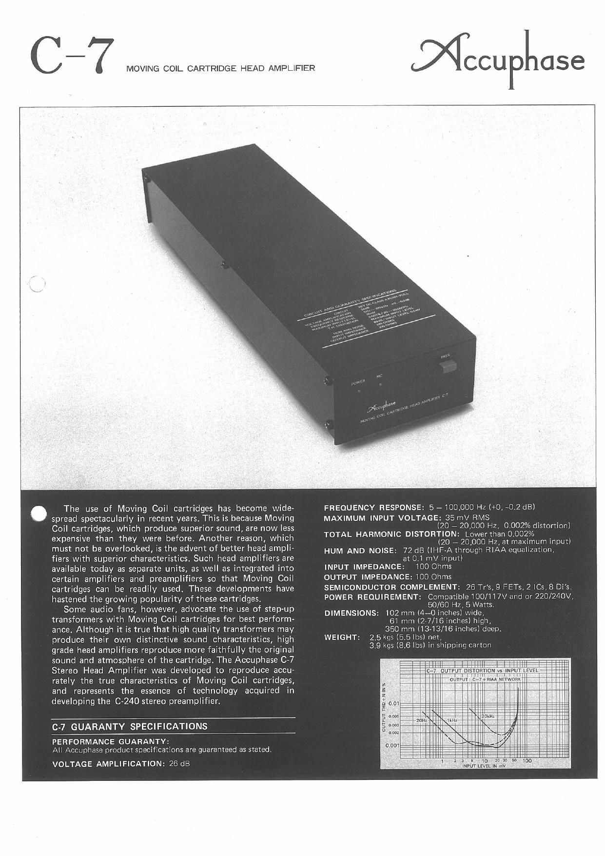
MOVING COIL CARTRIDGE HEAD AMPLIFIER
MCCUPIIGSG
The use of Moving Coil cartridges has become wide-
spread spectacularly in recent years. This is because Moving
Coil cartridges, which produce superior sound, are now less
expensive than they were before. Another reason, which
must not be overlooked, is the advent of better head ampli-
fiers with superior characteristics. Such head amplifiers are
available today as separate units, as well as integrated into
certain amplifiers and preamplifiers so that Moving Coil
cartridges can be readily used. These developments have
hastened the growing popularity of these cartridges.
Some audio fans, however, advocate the use of step-up
transformers with Moving Coil cartridges for best perform-
ance. Although it is true that high quality transformers may
produce their own distinctive sound characteristics, high
grade head amplifiers reproduce more faithfully the original
sound and atmosphere of the cartridge. The Accuphase C-7
Stereo Head Amplifier was developed to reproduce accu-
rately the true characteristics of Moving Coil cartridges,
and represents the essence of technology acquired in
developing the 0240 stereo preamplifier.
C-7 GUARANTY SPECIFICATIONS
PERFORMANCE GUARANTV:
All Accuphase product specifications are guaranteed as stated.
VOLTAGE AMPLIFICATION: 26 dB
FREQUENCY RESPONSE: 5 ~ 100.000 H1 H0, >02 dBl
MAXIMUM INPUT VOLTAGE: 35 mV RMS
(20 7 20,000 HI, 0
TOTAL HARMONIC DISTORTION: Lowertlian 0.002%
(20 # 20,000 Hi, at me mum input)
HUM AND NOISE: 72 dB UHF-A tliroiiuli FTiAAeriii laIUII,
at O 1 mV inpuil
INPUT IMPEDANCE: iOO Ohms
OUTPUT IMPEDANCE: 100 Ohms
SEM|CONDUCTOR COMPLEMENT 6 Tr's, 9 FETs, 2 ICs. 8 Di's.
POWER REQUIREMENT Compatible iOO/i i7\/ and or 220/240V.
50/60 H' 5Wans.
DIMENSIONS: i02 mm (IL-0 inch wi In
61 mm (27/16 in s) in i,
350 mm li3713/16 inches) deep.
2.5 ms [55 lbs) nor.
3, has (8.6 lbs) in shipping carton
listcrtionl
WEIGHT:
c-umn
o
2
ourruv ma + n IN as
.0
Page 2
MOVING CDII. ARTRIDGE HEAD AMPLIFIER
NccuPLase C- 7 _
1 SYMMETRICAL, CLASS-A PUSH-PULL,DC AMPLIFIER
UTILIZES RETs AT SIGNAL INPUT
The Accuphase C-7 Stereo Head Amplifier uses the same basic head
amplifier circuitry as the Accuphase C-240 as shown in Figure 1.
lt is a push-pull differential type, DC amplifier which employs four
RETs at the signal input, RET is the abbreviation for Ring Emitter
Transistor, which is constructed so that its internal circuit is equivalent
to a great many small signal transistors working together in parallel.
HETs were originally developed 'to provide power amplification for
superior high frequency characteristics. The Fl ETs used for the 07 were
further developed to ensure superior linearity at low operating levels.
Therefore, an ideal head amplifier input circuitry with exceptionally
low noise was achieved by utilizing their superior characteristics and
construction that makes an RET equivalent to a large network of many
transistors working in parallel.
2MAIN AMP CIRCUITS ENCAP-
SULATED INTO MODULES
The main amplifying circuits, includ
ing active devices and associated ele
ments are mounted on a printed board,
and encapsulated with special thermal
epoxy into separate modules channel
by channel. As a result these sections
are completely sealed off from air con-
tact which, not only ensures longer life,
but promises very stable operation
against wide temperature and humidity
changes.
3|CL (Input Capacitor-Less) SYSTEM FOR BETTER SOUND
Since a head amplifier's input circuits must handle extremely low
level signals, they must also have equivalent low noise characteristics.
The ordinary way to achieve this is to reduce input impedance to the
lowest value possible. This, however, requires a large input coupling
capacitor, and poses the problem of sound coloration, since it is difli~
cult to perfect large, high quality capacitors that do not introduce col~
oration.
To avoid the harmful effects of sound coloration. the input capac-
itors have been eliminated altogether in the C-7 by perfectly balanc~
irIg its input differential circuits. Therefore, highest fidelity can be
expected because the Moving Coil cartridge's low level output can be
fed directly to the C-7s FIET amplifying devices.
4LOW IMPEDANCE POWER SUPPLIES
Since the head amplifier must handle very small signals, it is the
power supply that controls its performance stability. Therefore, the O7
is provided with two voltage regulated power supplies, one each for the
left and right channels, that are located near the amplifier modules.
They ensure very stable operation as they maintain low impedance
characteristics over a wide range.
55Y-PASS SWITCH PROVIDED FOR OTHER TYPE
CARTRIDGES
A head amplifier is not required when Moving Coil cartridges are
not used, so a Berass Switch is provided which directly connects the
input and output terminals as shown in Figure 2. This permits the use
of other type cartridges without having to reconnect input pin plugs.
VOLTAGE
ntnutyon we
at _
vuLInGE
REGUtflOR ,DC
\J
Fig, 1. RETS' SYMMETRICAL PUSH>PULL,CLASS-A,DC AMPLIFIER
PASS-SWITCH
NF NETWORK
Fig, 2. DlAGRAM 0F C-7
RELATION BETWEEN CARTRIDGE OUTPUT IMPEDANCE
AND INPUT IMPEDANCE 0F HEAD AMPLIFIER
A head amplifier's input impedance becomes the load Imped-
ance of a Moving Coil cartridge that is connected to it. In othe
words, the cartridge represents the power generating element in
relation to its load which corresponds to the head amp' 5 input im»
pedance.
In such a relationship, the value of the load impedance must
not hinder the full operation of the power generating action.rThe
relatlon can be likened to that between an amplifier's output im-
pedance and the impedance of speaker. The general principle in
determinlng impedance values for best performance in such
relationships is that the load impedance should be several times
that of the output impedance.
An input impedance of 100 ohms was decided for this head
amplifier. it was chosen as a suitable load for the low 2 to 3- ohm
impedance type Moving Coil cartridges, as well as the high 40- ohm
impedance cartridges, as a result of extenslve listening tests with
all types of Moving Coil cartridges.
Sound quality is marred by a sense of oppression and bass
response is weakened when the load impedance becomes too low
This is because a load causes excessive damping against vibrations
of the cartridge' 5 moving elements
CCU 0 use
KENSDNIC LABORATORY INC.
LSOIUY
85li0023-00(BZ) PRlNTED IN JAPAN