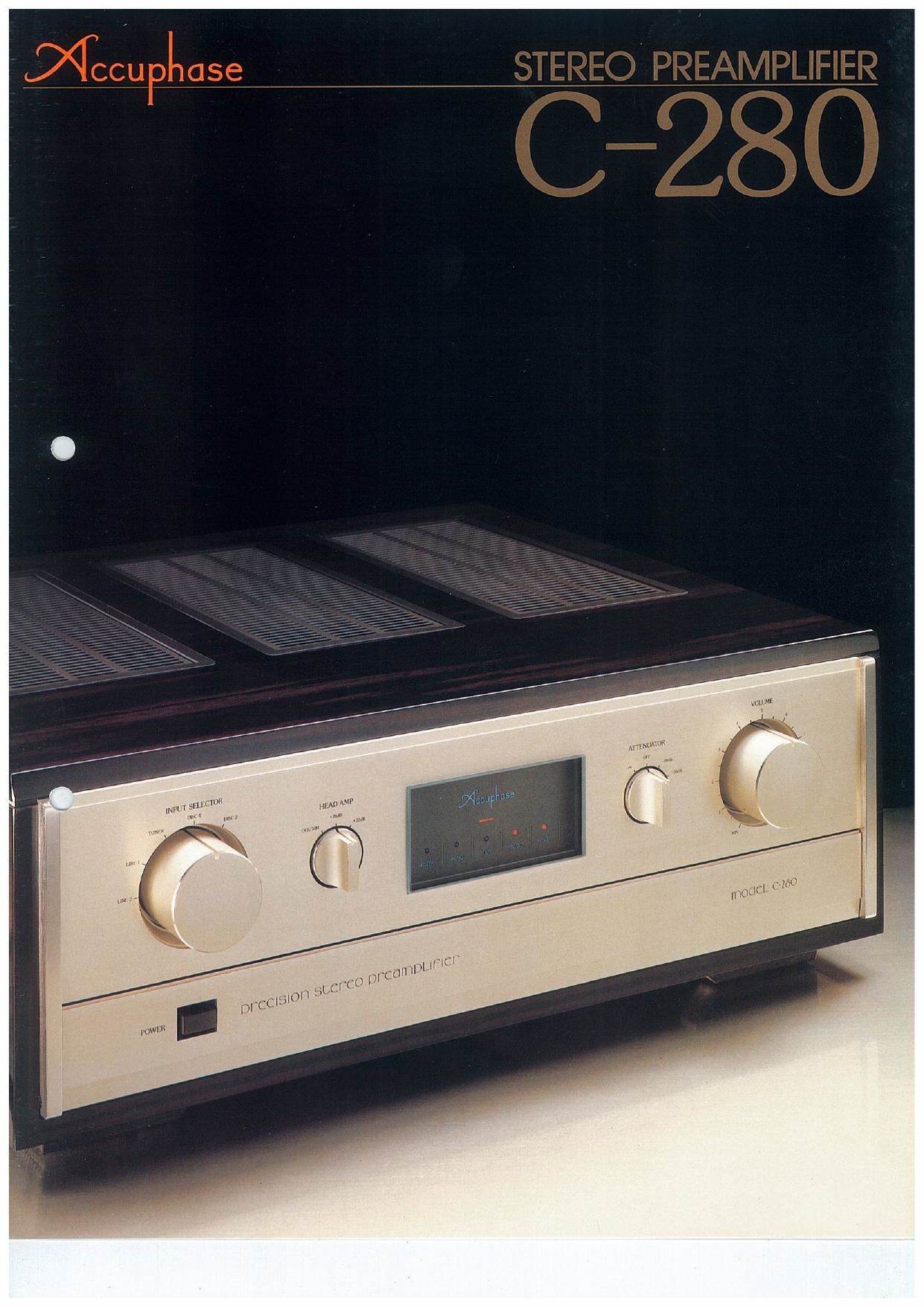
Accuphase C 280 Brochure

This is the 6 pages manual for Accuphase C 280 Brochure.
Read or download the pdf for free. If you want to contribute, please mail your pdfs to info@audioservicemanuals.com.

Page: 1 / 6
left right
Accuphase C 280 Brochure

Extracted text from Accuphase C 280 Brochure (Ocr-read)


Page 2

The advent of Compact Discs (CD), a new type of disc program
source. has raised the question of how they will compare in sound
quality with conventional discs that are based on the analog system, The
latter with its accumulated technology of a hundred years displays a
remarkably high standard in storing music and musical atmosphere, the
quality of which seems recently to be limited only by the ability of the
sound reproduction system employed to unlock its full potential. Beyond
a doubt, the near future will see keen competition between the two types
of disc sources to determine which will be recognized eventually as
superior from the high fidelity standpoint, '

Meanwhile. audiophiies of audio reproduction systems now have a
funher incentive to develop new techniques to continue improving music
reproduction technology

It is to meet this need of the times that the Accuphase 0-280
Preamplifier was developed. The main objective was to build a
preamplifier capable of preamplifying highest quality music reproduc-
tion signals from both analog and digital discs. and also to reveal the
individuality of turntables. tape recorders and speakers in a straight-
forward manner. Acouphase technology was thus concentrated on
recreating musical nuance signals in greater detail. and providing an
added sense of reality to musical reproduction. A total of six unit
amplifiers. three for each channel. are perfectly separated by a twin
monoaconstruction system. Furthermore, each unit amp is housed
separately, and is effectively shielded to produce superb, undistorted
amplified signals.

The tone control was eliminated to keep functions as simple as

possible. Only an irreducible minimum of function controls were
retained,

For the first time in the world. cascode pushepull amplification is
employed in every stage to achieve superior high frequency characteris-
tics and greatly improve linearity and signal-to-noise ratio. Also an ideal
multiple power supply system is used to provide each unit amplifier with
its exclusive power supply. This has ensured low impedance over a wide
range and superior amplification characteristics.

All devices that could affect sound quality were meticulously chosen,
and. where necessary. specially developed to ensure maximum sound
purity. Even wiring schemes and special plating for input/output
terminals were not neglected. The quality of line input was another area
given extra attention Thus. the 0280 was most carefully created to
preamplily both digital and analog discs and feed the best signal
characteristics to subsequent amplifiers

The C280 also provides better impedance matching for MC
(movingvcoil) phono cartridges. It also provides head amp gain
adjustment to cope with wide variations in MC cartridge output levels

The front panel has four main function control knobs that are
arranged symmetrically. while lesser function controls are found in the
subspanel.

The (3280 is enclosed in a handsome and impressive persimmon
wood cabinet. The elegant appearance and dignified simplicity in
design will persuade owners to cherish it for many years.

Accuphase firmly believes the 0-280 will provtde the Vista to new

dimensions in musical reproduction r

CASCOUE CLASS-A PUSH-PULL AMPLIFIER LINEUP GREATLY
IMPROVES HIGH FREQUENCY. LINEARITY and SIGNAL-TO-NOISE
CHARACTERISTICS

Ari amplifiers basic characteristics are largely determined by its
circuit configuration, In this sense, its circuit makeup is the most
important factor.

The 0-280 incorporates cascade amplification in addition to Accu-
phase's traditional use of Class-A Push-Pull Amplifiers in every stage,
This has further improved desirable amplifier characteristics to the
utmost limits before NFB (Negative Feedback) application.

Figure 1 shows the basic circuit of the cascode scheme used in the
0-280 in which the common emitter amp 01 and common base amp 02
are connected in series. The low input impedance of common base 02
ensures low output impedance and stabilizes operation. On the other
hand, Diode D regulates voltage and functions as bootstrap circuit
advantages which allow input impedance increases. and preserves high
gain and stable operation without distortion.

The cascode circuits distinctive features are low feedback and
excellent high frequency characteristics. It is an ideal amplifier since it
provides linearity over a device's entire operating range, reduces
distortion and improves signal-to-notse ratio. Moreover. the employment
of Class-A Push-Pull amplifiers in every stage further improves the
0280's basic circuit characteristics of linearity and low distortion before
NFB is applied,

Figure 2 shows the basic diagram of the unit amplifier. The same
circuit is used throughout for the head amplifier. the equalizer amplifier
and the high level amplifier Though appearing complex at first glance, it
is basically three stages of amplification, The eight devices from 02 to
09 make up the cascade push-pull differential amplifier stage. while
011 012. GM 015 on the one hand. and 016 to 019 are cascode
push-pull amp circuits. respectively. Combined they form a simple
amplification configuration of three stages that achieve maximum purity
and stability of amplified signals,

DC SERVO CONTROL IN ALL UNIT AMPS PERMIT STRAIGHT DC
OPERATION FROM MC INPUT TO FINAL OUTPUT
The lC in Figure 2 is the DC Servo Control circuit which eliminates DC
drift by backfeeding to the input any DC current that may appear at its
output The (37280 achieves a total maximum gain of 92 decibels Vet. all
its signal paths from the MC input to the final output are directly coupled
from one stage to the next in a straight DC operation This big advantage
is possmle because DC drift is completely eliminated by the elaborately
designed. effective DC Servo control circuits So there is a good reason
for the high quality sound characteristics that carry no trace of
coloration

TWIN MONO-CONSTRUCTED INDEPENDENT POWER
TRANSFORMERS; EACH UNIT AMPLIFIER HAS ITS EXCLUSIVE
POWER SUPPLY

The power supply can be considered a part of the amplifier circurt

since signals also pass through it. Therefore. unless its quality matches
that of the amplifier circuit. no improvement in overall sound characteris
tics can be realized.

The 0-280 employs twin power transformers which are both
completely independent. electrically and structurally. of each other. One
energizes the left channel and the other the right channel. Furthermore,
to achieve low impedance over a wide bandwidth, this preamplifier
employs an extravagant multiple power supply system conSistlng of Six
independent constant voltage power supplies. one for each of the unit
amps

Figure 3 shows such a power *-
supply for the equalizer amp unit. 09
010. 013 014, 011 Q12 and Ql5 --couwt
016. respectively make up high gain. . 02
cascode differential amplifiers which con-mm
ensure constant supply voltages. The 533,3? Ila
unit amps and their exclusive power ml 0
supplies are mounted in heavy alu- ,mmm

minum housings. Shortest signal
path leads are used to prevent in-
crease of power supply impedance Fig 1

at the WW frequenCIes Basic Circuit ofthe Cascade

Connection Amplifier O

.-

02 m I
-i I
as
aw .
+
0' om
m7. .1. , 1, W
04 an ii: J g. -
05 _ I
m l on m,

NFB
newton

Fig. 2 Basic Diagram of the Unit Amplifier

0 Unit Amplifier
(High-level Amplifier)