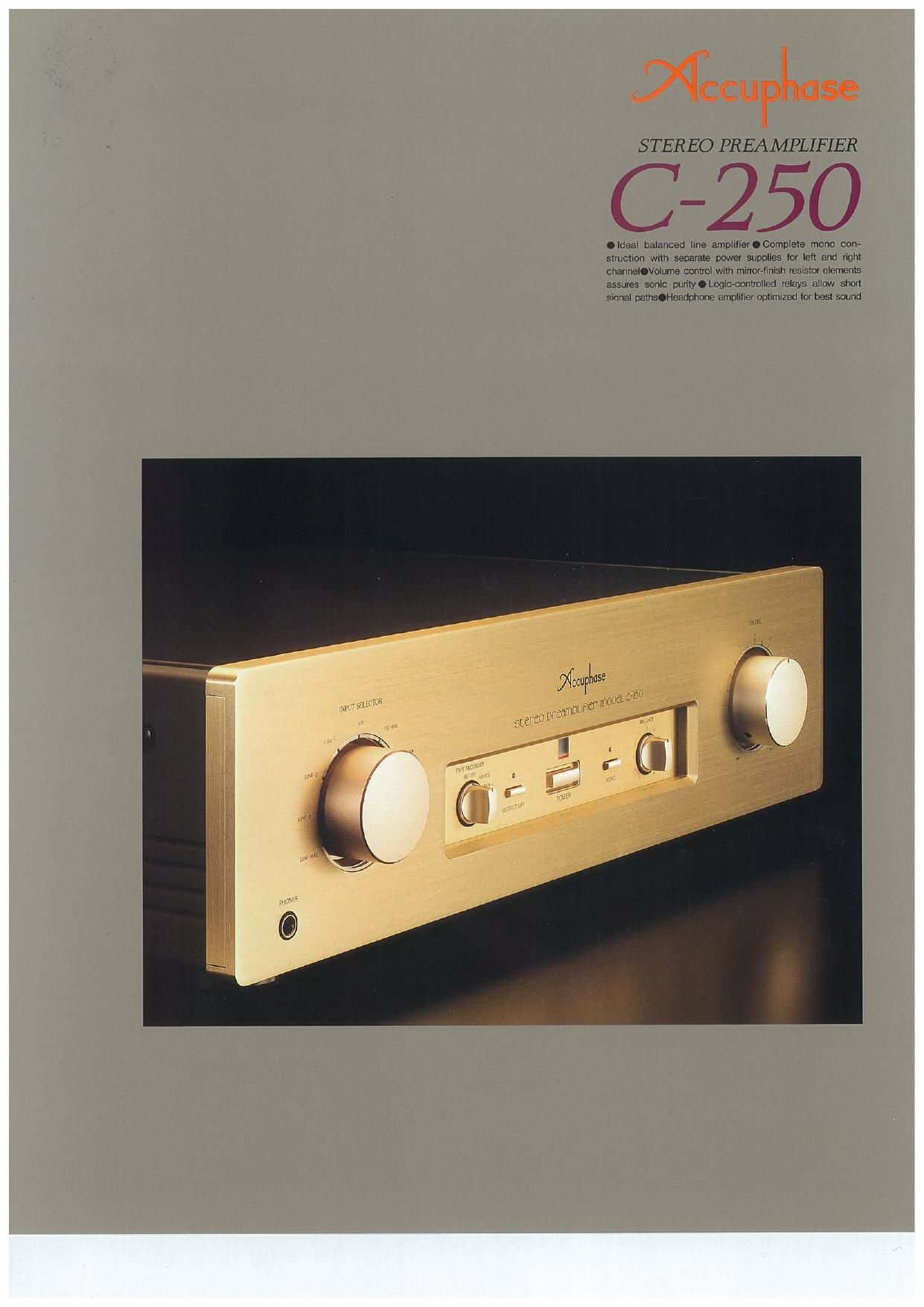
Accuphase C 250 Brochure

This is the 4 pages manual for Accuphase C 250 Brochure.
Read or download the pdf for free. If you want to contribute, please mail your pdfs to info@audioservicemanuals.com.

Page: 1 / 4
left right
Accuphase C 250 Brochure

Extracted text from Accuphase C 250 Brochure (Ocr-read)


Page 1

DqCCUP ase

STEREO PREAMPLIFIER

(3-250

.ldeal balanced line amplilierOComplele mono con-
strucxion with separate power supplies for leh and right
channeIIVolume control wilh minor-finish resistor elements
assures sonic purinOLogicwmlolled relays allow short
sinnal pthstHeadphone amplilier optimized lor best suund

Page 2

The 0-250 is a new addition to the distin-
guished line of Accuphase preamplifiers.
Based on balanced signal transmission tech-
nology developed by Accuphase, the circuit
design of the 0-250 has been kept deliberately
simple, and strictly selected parts and refined
performance assure outstanding sound quality.
In its standard configuration, the 0-250 is a
dedicated line amplifier, but Accuphase of
course has not forgotten the needs of audio-
philes with a cherished collection of analog
records The optional phono equalizer unit
AD-250 can be mounted in a special slot on
the rear panel, to allow high-grade analog disc
reproduction as well.

One of the main circuit features of the 0-250 is
its ideal line amplifier topology, which provides
equally excellent sound quality in balanced or
unbalanced operation The balanced output
stage employs symmetrically bridged feed-
back, resulting in a floating balanced topology.
where the signal is kept entirely separate from
the ground line This elaborate design lets the
amplifier develop its full potential.

The volume control is a mirror-polished resistor
type, and logic relay control allows desirably
short signal paths. With the supplied remote
commander, the user can switch sources and
adjust the volume from any convenient loca»
tion. A simple yet useful array of functions, and
parts and workmanship of the highest order
make the 0-250 a preamplifier that sounds
superb and is a joy to use,

Ideal Balanced Llne Amplifier

In balanced signal transmission, two identical
signals are transmitted simultaneously with
inverted phase and combined at the receiving
and, thereby canceling out common-mode
noise. High-frequency interference such as
caused by other electrical equipment cannot
intrude into the signal path or the power supply

Ideal line amplifier topology using bridged feedback.
Complete mono construction featuring separate
power transformers and unit amplifiers for left and
right channel. Volume control with mirror-finish
resistor elements assures smooth sound. High-quality
analog disc playback possible with optional phono
equalizer unit.

lines, keeping the sound absolutely pure.

Fig. 2 demonstrates the advantages of bal-
anced signal transmission as implemented by
Accuphase. (a) shows the circuit in balanced
operation and (b) in the unbalanced condition,
Basically. the unit consists of three differential
amplifiers. In balanced operation, the signal is
fed to the (+) and (it inputs of AMP1 and
subsequently to AMP2 and AMPS. The outputs
of these two amplifiers are connected to form a
cross-feedback loop, which sends the symmet-
rical (+) and (-) signals with low impedance to

, Inverted
lei

-« 5mm

" , Non-inverted

« wlpul

(a) Balanced input/output with floating ground

Invonad l. H Inverted

"\Wl W|Wi
5mm Q? a»; \"J j mom
Nell-illlloflaflk Jo

NDerwEflad

Input l I mint"

(bl Unbalanced input/output

n92 Comparison of balanced and
unbalanced signal transmission

the next stage. The signals do not depend on
the ground line, resulting in an ideal balanced
circuit. Even if one side of the output is ground-
ed, both amplifiers continue to operate, and the
output voltage does not change. Therefore the
circuit can accommodate an unbalanced input
or output connection simply by linking one side
to ground, without affecting signal amplifica-
tion characteristics, Fig, 3 shows the balanced
input circuit with its discrete differential push-
pull configuration. Fig. 4 is a circuit diagram of
the balanced output stage.

LlNE i

@-
must: ©---
©.
©__

LINE 2

LOGIC new comm

UNE: ©-
cc
We:
LINE
amnesia

war sstscrow were war mllEfi

Fig.1 Block diagram of 6-250 (one channel)


Inverted

o . a
d
input
pr 05
at as
0 output

c
Non-inverted 32 0

input as

i' .

Fig.3 Circuit diagram of balanced input amplifier

inverted
- output
AMP l
+
input HM,-
1 -4m-
.
AMP? . o
_ Non-inverted
output

fig.4 Circuit diagram of balanced output amplifier

Modular Construction With Totally Separate
Unit Amplifiers

The 0-250 contains a total of six unit ampli-
fiers, including the line amplifier, balanced
input amplifier and balanced output amplifier
for each channel, These units are housed in
thick enclosures made of extruded aluminum
and mounted to a sturdy motherboard. This
prevents interference among unit amplifiers
and guards against external vibrations and
resonances,

Complete Mono Construction With Separate
Transformers for Left and Right

The power supply section of the 0-250 also
spares no expense. Two sets of power trans-
formers and filtering capacitors are used in a
dual mono configuration, to preclude any pos-
sibility of electrical interaction between the
channels. This assures stereo reproduction of
the highest ordert

Volume Control With Mirror-Finish Resistor
Elements for Smooth Sound

The volume control is an important component
which can have a decisive influence on sound
quality. The 0-250 therefore uses special low-
distortion resistor elements with a mirror-like
surface. This ensures minimum contact resis-
tance and superior wear resistance. The con-
tact brush is gold plated and features a multi-
ple contact point design. The outer terminals
are integrated with the brush, to eliminate
superfluous metal links, thereby reducing dis-
tortion that can occur when different metals
come into contact. The contact brush is
designed to remain stationary: turning the vol-
ume knob rotates the resistor element assem-
bly. This innovative design drastically reduces