Accuphase A 100 Brochure

This is the 6 pages manual for Accuphase A 100 Brochure.
Read or download the pdf for free. If you want to contribute, please mail your pdfs to info@audioservicemanuals.com.

Page: 1 / 6
left right
Accuphase A 100 Brochure

Extracted text from Accuphase A 100 Brochure (Ocr-read)


Page 1

MECUPLOSG

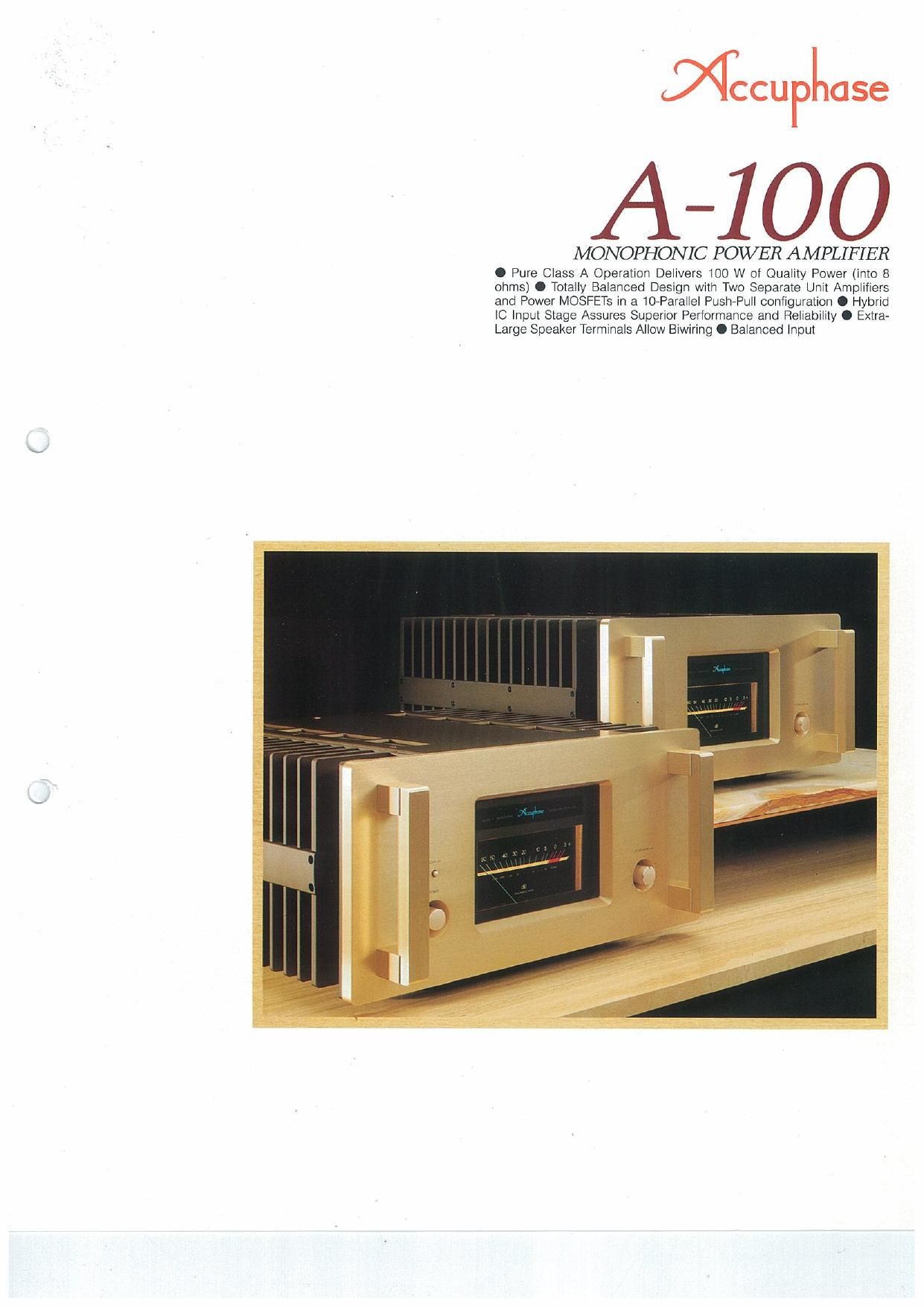
A-IOO

MONOPHONIC POWER AMPLIFIER

0 Pure Class A Operation Delivers 100 W of Quality Power (imo 8
ohms) 0 Totally Balanced Design with Two Separate Unit Amplifiers
and Power MOSFETS in a 10»Parailel Push-Pull configuration 0 Hybrid
IC Input Stage Assures Superior Performance and Reliability 0 Extra-
Large Speaker Terminals Allow Biwiring O Balanced input

Page 2

The A-iOO is an ultimate-quality component
that represents everything Accuphase stands
for. The entire wealth of Accuphases accumu-
lated know-how is incorporated in this pure
class A monophonic power amplifier, which
was designed to redefine the concept of im-
peccable music reproduction.

In pure class A operation, the power supply
delivers a steady current, regardless of the
presence or absence of a musical signal. This
means that the amplifier is unaffected by extere
nal influences and that its operation remains
highly stable under all circumstances But it
also means that the output stage generates
considerable thermal energy, commonly on the
order of more than 200 watts for an amplifier
rated at 100 watts output. In the A-100. this
figure is as high as 350 watts, and therefore
efficient heat dissipation is an absolute
necessity. This is why the A-tOO possesses
massive heat sinks on both sides which have
ample capacity to dissipate the heat produced
by the internal circuit components.

The guaranteed output power of the A~100
is 400 watts into 2 ohms, 200 watts into 4 ohms,
and 100 watts into 8 ohms. As these figures
indicate. the relationship between load impe-
dance and output power Is identical to the
theoretical values. In comparison to some other
amplifiers, a rating of 100 watts into 8 ohms
may seem small, but since the A-tOO will effort-
lessly drive even speakers of very low impe-
dance, there is absolutely no lack of power In
actual operation.

Power MOSFET Output Stage with Two Units in a lO-Parallel Push-PHIL

Configuration and Symmetrical Connection for Totally Balanced

Architecture. Pure Class A Operation Delivers 100 Watts of Quality Power

into 8 Ohms. Superb Drive Capability for Low-Impedance Loads,
with Ideal Power Progression of 200 Watts into 4 Ohms and

400 Watts into 2 Ohms. Balanced Input Stage with Hybrid IC for
Outstanding Performance and Long-Term Reliability.

The output stage uses power MOSFET
devices in a 10-parallel push-pull arrangement
with two separate amplifier units connected in a
bridged configuration, The balanced circuit
principle is maintained throughout. to assure
totally stable speaker drive.

The input stage employs a balanced differ-
ential pure complementary push-pull design
developed by Accuphase. This allows the
direct connection of a balanced input signal.
Even with an unbalanced connection. one side
of the input is connected to ground, allowing
direct connection of the signal without having
to use a phase inverter. A newly developed
hybrid IC with an alumina ceramic substrate is
used in the input stage of the A-tOO. yielding
outstanding temperature stability and long-
term reliability.

All energy delivered by an amplifier to the
speakers ultimately derives from the power
transformer and filtering capacitors of its power
supply. In the A-100, an over-dimensioned
toroidal transformer with a capacity of a lull
1kVA is used. together with two extra-large
68.000 uF capacitors, This results in a wide
performance margin and awesome current ca-
pacity that is virtually impossible to exhaust.
The transformer and capacitors are housed in
aluminum diecast enclosures to provide full
electrical and mechanical isolation and prevent
any possibility of sound quality degradation. In
order to support the enormous weight of the
power supply and heat sinks, the chassis and
front and rear panels of the A-100 are designed
to an almost excessive mechanical strength.

The large speaker terminals allow biwiring
and pure copper lead wires are employed to
complement high-quality. Signal path lines
such as printed circuit boards and buss lines
made of OFC (oxygen-free copper) are gold-
plated for absolutely pure signal transmission,

Every aspect of the A-100 has been finely
honed for nothing less than perfection. In a top-
quality system, this monophonic power ampli-

LOW Noise
PRECLSIDN mvunzn .

-+


PowER
sunny

1

Fig. 1 A400 Clrcult Diagram

fier will create a musical sound stage of awe»
inspiring authority.

Power MOSFET Output Stage With TWO
Units in to-Parallel Push-Pull Configuration
Delivers 400 Watts into 2 Ohms, 200 Watts
into 4 Ohms, 100 Watts into 8 Ohms

Fig. 1 shows the circuit diagram of the A400.
The N-channel power MOSFETs (QB. QB, 024)
and P-channel power MOSFETs (07, 09. 025)
are arranged in a 10-parallel push-pull configu-
ration. Two such units are connected in a
bridged configuration. The rated output power
is 100 watts into an B-ohm load, but since a
total of 40 MOSFETs are used in both the unit:
the total power dissipation is actually an amaz-
ing 4 kW. which leaves a more than ample
margin. MOSFETs are voltagecontrclled de-
vrces. Since the carrier of electrons is different
from that of bipolar transistors, MOSFETs have
good high frequency characteristics and a high
switching speed. The temperature coefficent of
a MOSFET is negative, which means that the
drain current does not increase With tempera-
ture, making the MOSFET free from curent con-
centration and thermal runaway. Unlike the
bipolar transistor, the second breakdown does
not take place in a MOSFET in the high voltage
region, and therefore, the MOSTFET can guar-
antee a wide area of safe operation.

In pure class A operation. the current
flowing through the active devices is always at
the value required for maximum output. and the
amplifier consequently produces a consider-
able amount of heat, The output devices there-
fore are mounted on a thick aluminum block
which in turn is mounted to the extra-large ex-
truded~aluminum heat sink.

Since the A-tOO is designed to deliver an
absolutely stable output of 100 watts into
ohms, its current capability into 4 and 2 ohms-
corresponds to the theoretical values. with 200
and 400 watts, respectively. Even into a load as
low as 1 ohm, the A~100 can deliver 560 watts
(measured). This assures stable drive of any
kind of speaker. including highly demanding
low-impedance types.

Totally Symmetrical and Balanced Circuitry
with Two Power Ampllfier Units

As illustrated by Fig. 2, there are two general
principles for audio signal transmission. Princi-
ple (a) is the so-called unbalanced principle
used in conventional audio components, (b) is
the principle of balanced signal transmission
which employs two identical amplifiers. The
circuit configuration of (a) is simpler, but there
is a distinct possibility of external noise being
picked up by the signal ground line, which can
lead to sound quality degradation. In the bal»
anced setup, separate lines are required for the
positive and negative signals. but any external
noise picked up by a signal line is cancelled by
principle. and even distortion components
arising within the amplifier are cancelled in the
output stage. leaving only the pure audio
signal. Therefore this is the ideal principle for
high»quality performance.

Page 5

FRONT PANEL
0 Power meter on/ofl switch
0 Power switch
9 Peak-reading power meter
(dB scale, direct wattagescale)
0 input level control
(up to -20 dB in 1-dB steps)

REAR PANEL
0 Unbalanced input jack (20 km
a Balanced input connector
XLR-3-31 or equivalent
(1): Ground (2): Inverted (e) (3): Non-inverted (4-)
Suitable connector: XLR-(HZC or equivalent
0 Speaker output terminals
0 input selector
UNBALANCED, BALANCED
9 AC power cord
0 Circuit breaker

Heat Sink, Chassis, and Panels Made from
Thick Aluminum for Optimum Rigidity

In class A operation, the power transistors of
an amplifier produce a considerable amount of
heat, which must be effectively dissipated. The
A400 therefore has large heat sinks which
have a total volume capacity of a full 164 liters
and weigh approximately 20 kg. The heat sinks
are tin-shaped to intensify natural cooling, and
a handle in the center helps to control vibra»
tions. The chassis which serves as a support
for the entire amplifier of course is also de-
signed tor extra strength. using 9 mm thick ex-
truded aluminum.

Aluminum Diecast Enclosure for Power
Transformer and Filtering Capacitors En-
sures Mechanical Stability

The power transformer in the A-100 is_ a high-
efliciency toroidal type encased in a thick alu~
minum diecast enclosure, to prevent vibrations
and other adverse effects from reaching the
outside. The enclosure is filled with a vibration
suppressing material of high heat conductivity.

The filtering capacitors are also housed in
similar cases with a strength of 4 mm. filled with
special anchoring material for electrolytic ca-
pacitors. Thanks to these precautions, the
power transformer and capacitors can work in
an optimum envi-
ronment without al-
fecting other parts
of the amplifier.

Extra-Large Speaker Terminals Allow Bi-
wiring

The amply dimensioned speaker binding posts
of the A400 can accommodate even very
heavyagauge speaker cables without prob-
lems, The terminals are made of a specially
pure brass with gold-plating, covered by

molded insulator caps. There are two parallel
sets of terminals. to permit biwiring (connect-
ing the low range drivers and mid/high range
drivers of a speaker with separate cables). The
electrodes are 2 mm thick oxygen-free copper
plates which are also gold-plated. The total
weight of the speaker terminal assembly alone
is more than 1 kg.

Peak Power Meter Calibrated in Decibel and
Watts

The large output level meter employs a loga-
rithmic scale which covers a wide dynamic
range. The peak indication allows quick and
accurate reading of power levels. The move»
ment and illumination of meter can be turned
off by an individual switch.