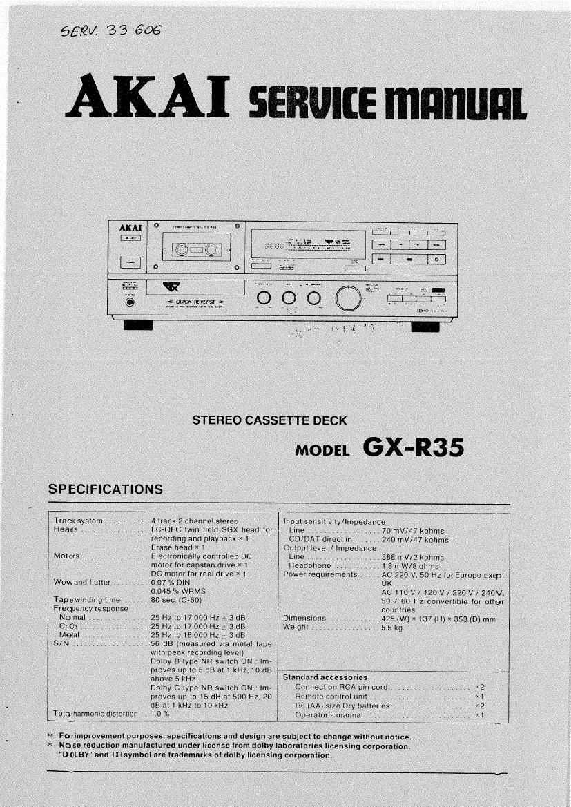
Akai GXR 35 Service Manual
This is the 24 pages manual for Akai GXR 35 Service Manual.
Read or download the pdf for free.
If you want to contribute, please mail your pdfs to info@audioservicemanuals.com.

Extracted text from Akai GXR 35 Service Manual (Ocr-read)
Page 2
* SAFETY INSTRUCTIONS
PRECAUTIONS DURING SERVICING
1. Fans identified by the is (*l symbol are critical lor
solely. Replace only wlth pans number specified.
2. in addition to satety. other parts and assemblies are
specitied tor contomarlce with such regulations as
those applying to spurious radiation.
These must also be replaced only with specttied rer
placements
Examples: RF converters, tuner units. antenna selector
switches. RF cables. noise Bloating capacltors. noise
blocking tillers, etc.
3 Use specified intemel wiring. Nola especially:
1) Wires covered with PVC tubing
2) Double insulated wires
5) High voltage leads
4. Use specified insulating materials tnr hazardous live
parts Note especially
I) Insulation tape
2) PVCtubing
a) Spacers (Insulating Barriers)
4) Insulation sheets tor transistors
5) Plastic screws Ior fixing microswitoh (especially in
turntable)
5 When replacing Ac primary side components (trans-
Iorrrrers. power cords, noise blocking capacitors etc),
wrap ends at wires securely about the terminals betore
soldering.
allele?
6. Observe that wires do not contact heat producing parts
(heasinks. oxide metal film resistors fusible resistors,
etc).
* INFORMATION
7. Check that replaced wires do not contact sharp edged
or poimed parts.
8. Also check areas surrounding repaired locations
9. Use care mat Iorotgn objects (screws. solder droplets,
etc.) do not remain inside the set.
SAFETY CHECKAFTERSERVICING
Alter servicing, make measurements of leakage-current or
resistance tn order to determine that exposed pans are
acceptably insulated from the supply circuit.
The leakage-current measurement should be done be-
tween accessible metal parts (such as chassis ground
terminal, microphone jacks, signal-inpm/outpul connectors,
etc.) and the earth ground through a resistor at 1500
ohms paralleled with a 0.15 uF capacitor, under the unit's
normal working conditions The leakage-current should be
less than 0.5 mA rms AC.
The resistance measurement should be done between at:-
cessible exposed metal pare and power cord plug prongs
with the power when (It Included) ON. The resistance
should be more than 22 Mohme.
MAKE YOUR CONTRIBUTION TO PROTECT
THE ENVIRONMENT
Used batteries with the ISO symbol for recy-
cling es well as small accumulators (re~ (D
chargeable batteries), mini-batteries (cells) %
and starter batteries should not be thrown
into the garbage can.
Please leave them at an appropriate depot All other
household batteries can be thrown out with the household
WESIBr
SYMBOLS FOR PRIMARY DESTINATION
Alphabet Indicates the destination of the units as listed
below
VOLTAGE CONVERSION (I Model only)
Betcre connecting the power cord. set the VOLTAGE SE-
LECTOR located on the rear panel with a liar type screw-
driver so that the correct voltage tor your area Is indi-
cated.
I. DISASSEMBLY
In case at trouble etct necessitating dismantling. please dismantle in the order shown in the illustrations.
Reassemble in reverse order.
1. Removal OI UPPER COVER
9'
v
If
FRONT PANEL
CASSETTE LID
It: Remove CASSEITE LID first. then remove FRONT
PANEL flexL
2. Removal of FRONT PANEL
4. Removal of MECHA BLOCK
Lln DECORATION
FIXATIott more
LI 0 DECORATION
1) Remove LID DECORATION while releasing LID
DECORATION FIXATION HOOKS.
2) Disconnect all the connectors which connected Irom the
MECHA. BLOCK,
3) Move the MECHA BLOCK GM 3 little. then pull out the
MECHA BLOCK trom rear side.
SERVICE uAuuAL
WW---