Akai GX 69 Service Manual
This is the 11 pages manual for Akai GX 69 Service Manual.
Read or download the pdf for free.
If you want to contribute, please mail your pdfs to info@audioservicemanuals.com.

Extracted text from Akai GX 69 Service Manual (Ocr-read)
Page 1
EE'XCI
SS'XB
AKAI some mnnunl
(ADDITIONAL)
Use this additional service manual together with the oreviouslv published service
manual for the AKAI GX-67 and DX-57 models.
For schematic diagrams and PC Boards, please refer to those provided tor the GX-
67 and DX-57 models.
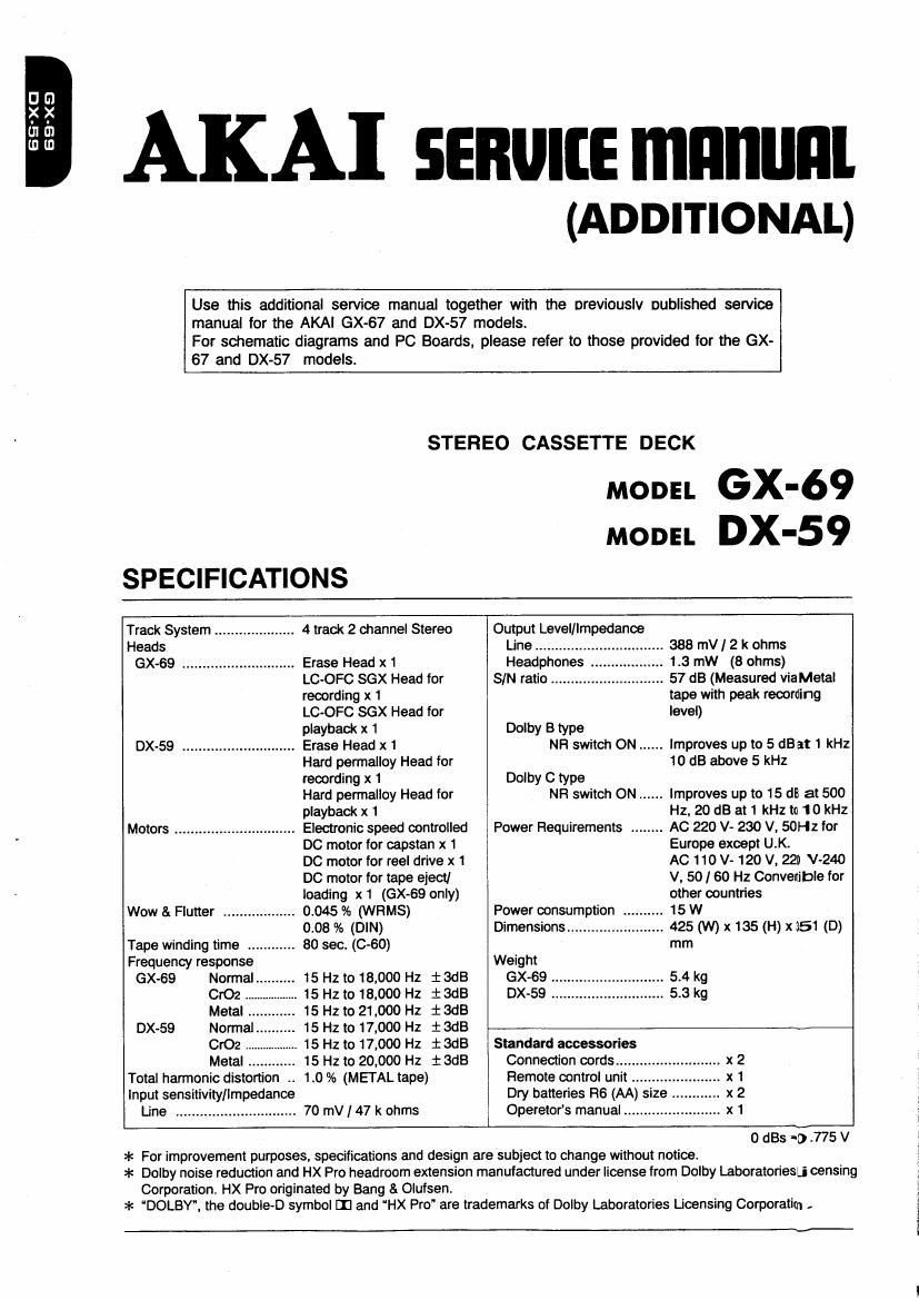
STEREO CASSETTE DECK
MODEL GX-69
MODEL DX-59
SPECIFICATIONS
Track System 4 track 2 channel Stereo Output Level/Impedance
Heads Line ................ 388 mV/ 2 k ohms
GX-69 ............................ Erase Head x 1 Headphones 1.3 mW (8 ohms)
LC-OFC SGX Head for SIN ratio ............ 57 dB (Measured via Metal
recording x 1 tape with peak recording
LC-OFC SGX Head for level)
playback x 1 Dolby B type
DX-59 ............................ Erase Head x 1 NH switch ON ...... Improves up to 5 dB at 1 kHz
Hard permalloy Head for 10 dB above 5 kHz
recording it 1 Dolby C type
Hard pennalloy Head for NH switch ON ...... improves up to 15 dll at 500
playback x 1 Hz, 20 dB at 1 kHz to 1 0 kHz
Motors Electronic speed controlled Power Requirements ........ AC 220 V- 230 V. 50Hz for
DC motor for capstan x 1 Europe except U.K.
DC motor for reel drive x 1 AC 110 V 120 V. 22] V~24O
DC motor for tape eject] V, 50/60 Hz Convenibie for
loading x 1 (GX-69 only) other countries
Wow & Flutter .................. 0.045 % (WRMS) Power consumption . 15 W
0.08 % (DIN) Dimensions ............... 425 (W) x 135 (H) x151 (D)
Tape winding time ............ 80 sec. (660) mm
Frequency response Weight
GX-GQ Normal 15 Hz to 18,000 Hz i adB GX-69 .. 5.4 kg
. 15 Hz to 18.000 Hz iadB DX-59 .. .. 5.3 kg
. 15 Hz to 21,000 Hz iadB
DX-59 15 Hz to 17,000 Hz iSdB
. 15 Hz to 17,000 Hz i SdB Standard accessories
. 15 Hz to 20,000 Hz : SdB Connection cords ......
Total harmonic distortion to 1.0 % (METAL tape) Remote control unit ..
Input sensitivity/Impedance Dry batteries FIG (AA) size ..
Line .............................. 70 mV / 47 k ohms Operators manual .o x 1
0 st 1) .775 V
=l< For improvement purposes. specifications and design are subject to change without notice,
=l< Dolby noise reduction and HX Pro headroom extension manufactured under license from Dolby Laboratoriesu censing
Corporation. HX Pro originated by Bang 8t Olufsen.
* DOLBY. the double-D symbol III and HX Pro" are trademarks of Dolby Laboratories Licensing Corporatim -
Page 2
I. PARTS LIST
HOW TO USE THIS PARTS LIST
1. This Parts List lists those parts which are considered necessary for repairs. Other common parts, such as resistorsand ca-
pacitors, are listed in the Common List for Service Parts" from which these parts should be selected and stocked.
2. The Recommended Spare Parts Listshows those parts in the Parts List which are considered particularly importantfor ser-
vice
3. Parts not shown in the Parts List and Common List for Service Parts will not in principle be supplied.
4. How to read the Parts List.
a) Mechanism Block D) PC Board
2. HEAD BASE BLOCK 6. MAIN PC BOARD
Rel . . FIeI . ,
No, Part No Description No Part No. Description
1 BH-T2023A320A HEAD BASE BLOCK ICI EI-324535 IC HD140498P
2 HP-H2206A010A HEAD FI/P PH4-BFU C |C2 El-336801 IC MBBBMASGAM
3 28477876 PANZOIOSSTL CMT C1A EC-338399 C MMY V 223M 250AC IUI,BS]
4 23536488 BID201038TL CMT C13 EC-350949 C MMY V 223M 2500C [J]
§ $402895 SP CS ANGLE ADJUST 01C EC-338397 C MMY V 223M 125M: [CA]
g E-318384 OSC X'TAL NC»IBC
L SP (Service Parts) Classification
. I . . , Symbols lor primary destination «T
This number corresponds With the IndIVId
_ . [A] :AAL (U.S.A) [S] :SAA (Australia)
ual Parts "59" "umber " 3 figure [a] :BEAB (Englandl [U] :U/T (UniveIsal Area)
[C] :CSA (Canada)
[E] :CEE (Europe) [V] :VDE (Germany)
[J] :JPN (Japan) (Y1 :Custom Version
SP (Service Parts) Classification
These reference symbols cones pond
with component symbols in the
Schematic Diagrams
The available PC Board Blocks are listed separately.
5. When Part No. is known, Parts Index at end of Parts List can be used to locate where that part is shown in Parts
List by its Reference No.listed at right of Pan Not
A (*1 INDICATES SAFETY CRITICAL COMPONENTS. FOR CONTINUED SAFETY, REPLACE SAFETY
CRITICAL COMPONENTS ONLY WITH MANUFACTURES R
AVERTISSEMENT
moi) IL INDIQUE LES couposms CRITIQUES DE sewnrré. POUR MAINTENIB LE 05665 DE
SECURITEDE LAPPAFIEIL NE REIIIPLAcen one pas PIECES Recoumnoees vim
FABRICANT.
PARTS LIST