Akai GX 65 Mk2 Service Manual
This is the 30 pages manual for Akai GX 65 Mk2 Service Manual.
Read or download the pdf for free.
If you want to contribute, please mail your pdfs to info@audioservicemanuals.com.

Extracted text from Akai GX 65 Mk2 Service Manual (Ocr-read)
Page 1
© .ma-u... aw ©
9.
cg
Oil-l0 MW
:1
W ::=.==::MW T"
©éii I [E
mammal-[Mun
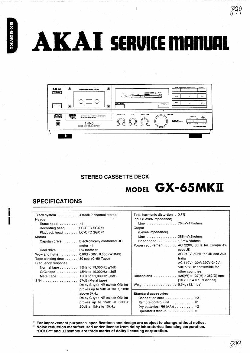
STEREO CASSETTE DECK
moon GX-65MK]I
SPECIFICATIONS
Track system ............ 4 track 2 channel stereo Total harmonic distortion . 0.7%
Heads \ Input (Level/Impedance)
Erase head ............ )(1 Line ................. 70mV/47kohms
Recording head . LC-OFC SGX X1 Output
Playback head ......... LC-OFC SGX X1 (Level/Impedance)
Motors Line ................ 388mV/2kohms
Capstan drive ......... Electronically controlled DC Headphone t . t 13mW/80hms
motor X1 Power requirement ....... AC 220V 50Hz for Europe ex-
Fleel drive ............. DC motor Xi cept UK
Wow and flutter .......... 006% (DIN), 0.035 (WRMS) AC 240V, 50Hz for UK and Aus-
Tape winding lime ........ 80 sec. (0-60 Tape) tralla
Frequency response AC 110V-120W220V-240V.
Normal tape ...... . . 15Hz to 19.000Hz tadB 50Hz/60Hz convertible for
002 tape ........ .r 15Hz to 19,000Hz tSdB other countries
Metal tape ....... ,. 15Hz to 21 ,OOOHZ tSdB Dimensions ............. 425(W) x 1370-!) X 353(0) mm
S/N ................ .t 57dB (Metal tape) (16.7 x 5,4 x 13.9 inches)
Dolby B type NR switch ON: im- Weight ................. 5.5kg (121 lbs)
proves up to SdB at 1kHz, 10dB
above 5kHZ Standard accesories
DOIbY C W99 NR SWitch 0N: lm- Connection cord ............... xz
proves up to 15dB at SOOHZ. Remote control unit ............. X1
20:38 at (Hz to 10kHz
Dry batteries (R6 (AA)) i. xz
Operators manual .............. X1
For improvement purposes, specifications and design are subiect to change without notice.
Noise reduction manufactured under license from dolby laboratories licensing corporation.
DOLBY and III symbol are trade marks of dolby licensing corporation.
975?
Page 2
* SAFETY INSTRUCTIONS
PRECAUTIONS DURING SERVICING
1. Parts identified by the A (*) symbol are critical for
safety. Replace only with parts number specified.
2. In addition to safety, other parts and assemblies are
specified for conformance with such regulations as
those applying to spurious radiation.
These must also be replaced only with specified re-
placements.
Examples: FiF converters, tuner units, antenna selector
switches, RF cables, noise blocking capacitors, noise
blocking filters, etc.
3. Use specified internal wiring. Note especially:
1) Wires covered with PVC tubing
2) Double insulated wires
3) High voltage leads
4. Use specified insulating materials for hazardous live
parts. Note eSpecially:
1) Insulation Tape
2) PVC tubing
3) Spacers (Insulating Barriers)
4) insulation sheets for transistors
5) Plastic screws for fixing microswitch (especially in
turntable)
5. When replacing AC primary side components (trans-
formers, power cords, noise blocking capacitors, etc),
wrap ends of wires securely about the terminals before
soldering.
sale)?
6. Observe that wires do not contact heat producing parts
(heatsinks, oxide metal film resistors. fusible resistors,
etc).
* INFORMATION
\
7. Check that replaced wires do not contact sharp edged
or pointed pans.
. Also check areas surrounding repaired locations
9. Use care that foreign objects (screws, solder droplets,
etc.) do not remain inside the set.
on
SAFETY CHECK AFTER SERVICING
After servicing. make measurements of leakage-current or
resistance in order to determine that exposed pans are
acceptably insulated from the supply circuit
The leakage-current measurement should be done be-
tween accessible metal parts (such as chassis, ground
terminal, microphone jacks, signal-input/output connectors,
etc.) and the eanh ground through a resister of 1500
ohms paralleled with a 0.15 pF capacitor, under the unit's
normal working conditions. The leakage-current should be
less than 0.5 mA rms AC.
The resistance measurement should be done between ac-
cessible exposed metal parts and power cord plug prongs
with the power switch (if included) ON. The resistance
should be more than 2.2 Mohms.
MAKE YOUR CONTRIBUTION TO PROTECT
THE ENVIRONMENT
Used batteries with the ISO symbol for recy- (D
and starter batteries should not be thrown &
into the garbage can.
Please leave them at an appropriate depot All other
cling as well as small accumulators (re-
chargeable batteries), mini-batteries (cells)
household batteries can be thrown out with the household
waste.
SYMBOLS FOR PRIMARY DESTINATION
Alphabet indicates the destination of the units as listed
below.
Principal Destinations
USA
U K
Canada
Europe (e
Japan
Australia
W.
Universal Area
Custom version
SERVICE MANUAL
VOLTAGE CONVERSION (El Model only)
. Before connecting the power cord, set the VOLTAGE SE-
LECTOFl located on the rear panel with a flat type screw-
driver so that the correct voltage for your area is indi-
cated.
bJI-I
VOLTAGE
SELECTOR