Akai GX 625 Service Manual
This is the 76 pages manual for Akai GX 625 Service Manual.
Read or download the pdf for free.
If you want to contribute, please mail your pdfs to info@audioservicemanuals.com.

Extracted text from Akai GX 625 Service Manual (Ocr-read)
Page 2
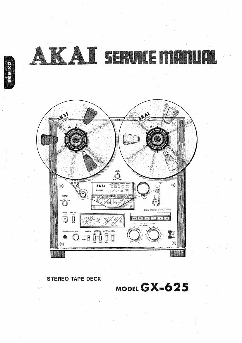
STEREO TAPE DECK
MODEL GX' 62 5
ALSO APPLICABLE TO BLACK PANEL MODEL 1
SECTION 1 SERVICE MANUAL ................ I. . . . 3
SECTION 2 PARTS LIST .......................... 47
SECTION 3 SCHEMATIC DIAGRAM ................ 70
Page 27
5509 1501;
Fig. 28
BRAKE PLUNGER
Fig. 27
X 0.5 to LOmm
Fig. 29
5. BRAKE BAND POSITION ADJUSTMENT
AND BRAKE TENSION ADJUSTMENT
(Refer to Figs. 27 to 29)
1) Adjust the brake lever to 180° position by loosen~
ing the screws (3) and (a). '
2) Work the brake plunger to check that the brake
band is not slanted. J
3) Adjust the position of the part with screws (13) and
(b') to obtain a brake tension of 550 i 50g on
both brakes at stop mode.
(Use a 1,000 g Spring gauge for a reel with 60 mm
diameter of tape.) In case the specified brake
tension cannot be obtained, connect the springs to
the other holes on the brake lever and adjust.
4) By working the brake plunger with a finger, adjust
the position of the microswiteh screw (0) so that
the gap between the brake lever and the micro
switch body is 0.5 to 1.0 mm.
26'
Page 29
. TAPE SPEED ADJUSTMENT
1 (Refer to Fig. 32)
Set the Tape Speed Switch to 7~1/2 ips and playback
the 1,000 Hz, 7-1/2 Test tape. Connect a frequency
counter to LINE OUT and adjust VR2 20 kB until
the counter reads 1,000 Hz i 0.5%.
Next, set the Tape Speed Switch to 3-3/4 ips and
adjust VRl 50 kE until the frequency counter reads
500 Hz i 0.5%.
Fig. 32
28