Akai GX 32 Service Manual
This is the 23 pages manual for Akai GX 32 Service Manual.
Read or download the pdf for free.
If you want to contribute, please mail your pdfs to info@audioservicemanuals.com.

Extracted text from Akai GX 32 Service Manual (Ocr-read)
Page 1
690
AKAI senmre mnnunl
m} 0 mm» m: o a wwwmm
:: m- _. ,
E omo m u -1 - ~
M 30;.- S 7. 4:. - [3."
3? Q (j\ Q ,IOi. s... n: w .7.
© 0 vmrmmw o - m. , . ,V - V
.- 3.
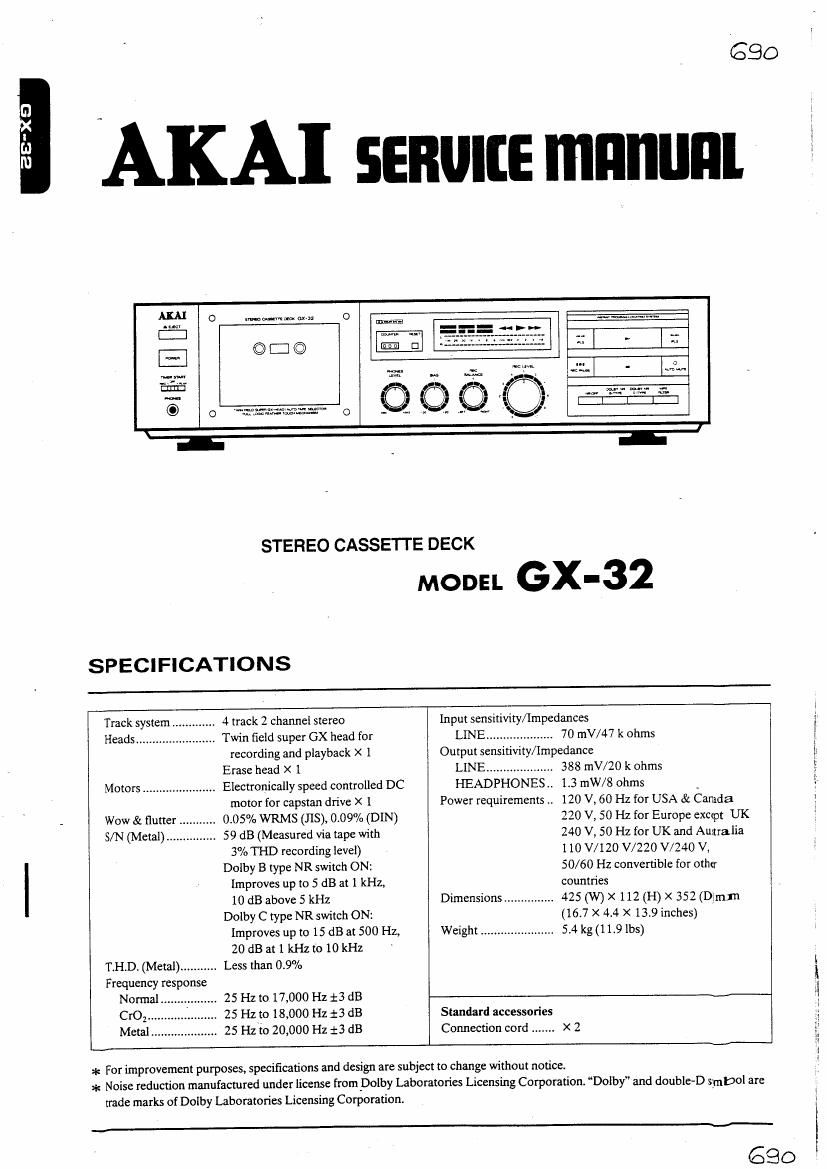
STER E0 CASSETTE DECK
MODE L GX - 32
SPECIFICATIONS
Track system .. 4 track 2 channel stereo Input sensitivity/Impedances
Heads ........... .. Twin field super GX head for LINE ................... 70 mV/47 k ohms
recording and playback X 1 Output sensitivity/ Impedance
Erase head X 1 LINE .................... 388 mV/20 k ohms
Motors ................... Electronically speed controlled DC HEADPHONES .. 1.3 mW/S ohms _
motor for capstan drive X 1 Power requirements .. 120 V, 60 Hz for USA & Canada
Wow & flutter ........... 0.05% WRMS (118), 0.09% (DIN) 220 V, 50 Hz for Europe eXCtpt UK
S/N (Metal) ............... 59 dB (Measured via tape with 240 V, 50 Hz for UK and Autralia
3% THD recording level) I 10 V/ 120 V/ 220 V/240 V,
Dolby B type NR switch ON: 50/60 Hz convertible for other
Improves up to 5 dB at 1 kHz, countries
10 dB above 5 kHz Dimensions ............... 425 (W) X 112 (H) X 352 (Dlmjn
Dolby C type NR switch ON: (16.7 X 4.4 X 13.9 inches)
Improves up to 15 dB at 500 Hz, Weight ...................... 5.4 kg(11.9 lbs)
ZOdBatl kHzto IOkHz
T.H.D. (Metal) ........... Less than 0.9%
Frequency response
Normal 25 Hz to 17,000 Hz 13 dB
00;. 25 Hz to 18,000 Hz i3 dB Standard accessories
Metal .................... 25 Hzm 20,000 Hz :3 dB Connection cord ....... x 2
* For improvement purposes, specifications and design are subject to change without notice.
~,.-,.
* Noise reduction manufactured under license from Dolby Laboratories Licensing Corporation. Dolby" and double-D smbol are
trade marks of Dolby Laboratories Licensing Corporation.
690
Page 2
*SAFETY INSTRUCTIONS
PRECAUTIONS DURING SERVICING
1. Parts identified by theA(>l<) symbol parts are critical for
safety. Replace only with parts number specified.
. In addition to safety. other parts and assemblies are speci~
to
. Check that replaced wires do not contact sharp edged or
pointed parts.
. Also check areas surrounding repaired locations.
tied for conformance with such regulations as those apply- 9. Use care that foreign objects (screws, solder droplets, etc.)
ing to spurious radiation. do not remain inside the set.
These must also be replaced only with specified replace-
ments. SAFETY CHECK AFTER SERVICING
EmmPICS: RF converters, tuner units, antenna selector Confirm ' the specified insulation resrstance between power
switches, RF cables. noise blocking capacitors. noise block- cord plug prongs and externally exposed parts of the set is
mg filters, etc. . greater than 10 M ohms. but for equipment with external an-
3' Use SPCCifiEd internal wiring. N9: espectally: . tenna terminals (tuner. receiver. etc.) and is intended for C or
1) Wires covered mm/C tubing A . specified insulation resistance should be headphone jacks
2) Double insulated wtres lineAin-out jacks etc. more than 2.2 M ohms (ground terminals.
3) High voltage leads microphone jacks).
4. Use specified insulating materials for hazardous live parts.
Note especially:
1) Insulation Tape
2) PVC tubing
3) Spacers (Insulating Barriers)
4) Insulation sheets for transistors
5) Plastic screws for fixing microswitch (especially in turn-
table)
. When replacing AC primary side components (trans-
formers. power cords, noise blocking capacitors. etc.). wrap
ends of wires securely about the terminals before soldering.
denial
6. Observe that wires do not contact heat producing parts
(heatsinks, oxide metal film resistors, fusible resistors. etc.).
on
air INFORMATION
SYMBOLS FOR PRIMARY DESTINATION VOLTAGE CONVERSION (U Model only)
Alphabet indicates the destination of the units as listed below. Before connecting the power cord. SET the VOLTAGESE-
LECT OR located on the rear panel with a screwdriver sothat
Symbols Principal Destinations the correct voltage is indicated.
m USA
[3 UK i
[1'] Canada 3i
[E] Europe (except UK) i
m Japan 5
ES] Australia 322%; i
[ll W. Germany only s utw i
[17'] Universal Area '
m Custom version
SERVICE MANUAL