Akai GX 280 DSS Service Manual
This is the 68 pages manual for Akai GX 280 DSS Service Manual.
Read or download the pdf for free.
If you want to contribute, please mail your pdfs to info@audioservicemanuals.com.

Extracted text from Akai GX 280 DSS Service Manual (Ocr-read)
Page 1
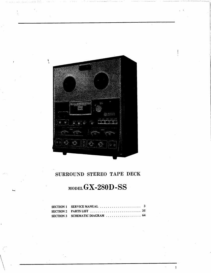
SURROUND STEREO TAPE DECK
MODEL GX'280D ' SS
SECTION I SERVICE MANUAL ..................... 3
SECTION 2 PARTS LIST .......................... 35
SECTION 3 SCHEMATIC DIAGRAM .................. 64
Page 10
IV. MECHAN ISM ADJUSTMENTS
SERVO CONTROL
AMF. EC. BOARD
LI VlzoalSC-Ol
VR 202 2KB
1. TAPE SPEED ADJUSTMENT
i
(Servo Control Amp, Adjustment)
1) Connect a frequency counter to the Line Out-
puts as shown in Fig. 1.
2) Depress 3-3/4 ips (9.5 cm/sec.) Tape Speed Selec-
tor Switch and playback a 1,000 Hz pie-recorded
test tape.
3) Adjust the core of coil L1 (VIO23SC-01) shown
in Fig. 8 to obtain a frequency counter indica-
tion of 500 Hz il%.
4) After the 3-3/4 ips (9.5 cm/sec.) tape speed
adjustment has been completed, depress the 7-1/2
ips (19 cm/sec.) Tape Speed Selector Switch and
adjust Servo Control P.C. Board semi-fixed resistor
VR202 (2 kB) shown in Fig. 8 to obtain a
freQuency counter indication of 1,000 Hz +l/
-0.5%.
NOTE: When making tape speed adjustment, it is
necessary to make the low Speed (3-3/4 ips)
adjustment first. .
SYSTEM CONTROL
PC. BOARD
VRlOI IOKB
VRIOZ 10KB
Fig. 8
2. DIRECT FUNCTION TIME CONSTANT
ADJ U STMENT
1) FWD e REV Time Constant
Adjust System Control P.C. Board semi-fixed
resistor VRlOl (30 kB) shown in Fig. 8 so that
when the machine is switched from FWD to REV
mode or. from REV to FWD mode, the pinch
wheel separates from the capstan in about 3
seconds.
2) Adjust System Control P.C. Board semi-fixed
resistor VR102 (10 k8) shown in Fig. 8 so that
when the machine is switched from F.FWD or
RWD to FWD or REV mode, the time constant
is about 1.5 seconds.
NOTE: When making adjustments outlined in Items
2. 1) and 2. 2) above! when the machine is
switched from the various modes to FWD
or REV, confirm that correct capstan motor
(servo motor) revolutions are reached by
the time the pinch wheel contacts the
capstan.
10
Page 21
FRONT LEFT FRONT RIGHT
OUTPUT SIGNAL'B'gv rag OUTPUT SIGNAL
i». dz
OSCILWSCOPE
IN PHASE Fig. 29
Fig. 28
ouT- OF PHASE Fig- 30
HIGH
SENSITIVITY
V.T. V. M.
RON LEFT 1"
T
ou PUT SIGNAL;
~FRONT RIGHT a
OUTPUT SIGNAL _>_...___.
6. 4-CHANNEL PHASE CHECK
Method A
1) Connect front left signal and from right signal
from the line output terminal to vertical and
horizontal input terminal of Oscilloscope. (See
Fig. 28)
2) Playback a 250 HZ O VU pre-recorded test
tape at 7-1/2 ips.
3) If front left and front right are In-Phase, the
Waveform as shown in Fig. 29 will appear on
the oscilloscope screen.
4) If phase is 180° out of phase, a waveform as
shown if Fig. 30 will appear on the oscilloscope
screen.
5) Make the same check on front left/rear left and
rear left/rear right.
6) The line outputs should be In-Phase, if not, Re-
cording/Playback Head needs adjusting.
IN PHASE. +443
OUT-0F PHASE -5dB Fig. 31
Method B (See Fig. 31)
1) Playback a 250 Hz 0" VU pre-recorded test
tape at 7-1/2 ips.
2) Connect front left signal and front- right signal
of line outpUt terminals in parallel and connect
this to a high sensitivity V.T.V.M. (Model 161A).
3) If In-Phase, the line output will be about +4 dB.
4) At 180° out of phase, the line output will be
about #5 dB.
5) Make the same check on front left/rear left and
rear left/rear right.
21
Page 41
FIG. 4. ILLUSTRATION OF MECHANISM ASSEMBLY BLOCK ( 1)
7
7
6 H
7 11
H
11 5
7 H
5 1
6 H
M H
M H
5 4
2 3
5
127 $7
22 1
47 9
4 8
4 8
4 11
M
4 15
12 123
51 119
N 2
H
3 4
3 101
M
4
5
6 42
15 156
79
is 110
10 5
15 6
10 1
5 0
14 75
£4 4
s 5
H M
56 140
H8
138
7
13 W
50 134
60 130
Z: 136
61 135
R
IN
133
N2
MECHANISM ASSEMBLY BLOCK (1)
2:" Puts No. 5 I Description ,3? Qty 53? Paris Nov Description S;.':_'Qty
PINCI-I ROLLER PLUNGER BLOCK BRAKE PLUNGER BLOCK
4-1x 132428940 Pinch Roller Plunger Block 1.ng 32393333 Brake Plunger Block Comp. KF.KD.KH 1
Comp. KF-KGiKA 1 4-20 EP393610 Plunger Solenoid '
4-2 EP441990 Plunger 1660THTI Solenoid 44-1-45 1 spc.1o.M_c.1oov 44-1-35 1
4-3x ER376424 Spark Quencher U/L 4-21x ER376424 Spark Quencher U/L
0.11.1+120 SDOWV 11-145 1 0.1114420 soowv 41-1-35 1
44 M23969 Plunger Bracket Kin-102s. 1 4.22 1423959 1 1 Plunger Bracket' ' mm 1
4-5x zw323\728 Screw. binding head 3x5 3 4-23x ZW20183S Screw, binding head 3x5 4
4-6 MZS96922 Black Mask 2 lib-1029 1 4.24 M2396977 Brake Plunget Joint Ku-lm 1
4-7 ZW417137 SereW. binding head 3x4 2 4-25 zwzs7477 Connecting Pin run-211 1
4-8 MZ428343 KD Stopper Rubber 3'10 2 41-2611 ZW270088 E Ring 1.9M 6-1-9 I
4-9 M2396966 Plunger Joint, w/pln KD-lbaa 1
4-10 ZW257477 Connecting Pin RD-ZII 1
4-1 1 M2396944 Pinch Roller Arm Joint Ku-lnal l SENSING GUIDE BLOCK
4-12x 2W270088 E Ring 1.9M 5+9 1 4-27x 32398362 Sensing Guide Block Comp. Knxu 1
4-13x ZW345442 Washer (Nylon) D4.2x9x1t 1 4-28 MZSQGSSI Sensing Table. w/prop KD-zim . 1
4-14x ZW270101 E Ring 3M 6-1-5 1 4-29 M2396573 Insulator Collar B KD-m23 1
4~15 M2396933 Pinch Roller Arm, w/shafl ID-1°30 1 4-30 M2397203 Séi:sing Pole Terminal Plnle KD-mz 1
4-16 ZW273960 Nut, M4 3 4-31 26396516 Tape Guide Adjust Spring KD-ZMA I
4-17 MZBOZ9BO Spring Holder DID-275 2 4-32 M2396517 Sensing Guide B Knezozs 1
4-18 ZG428927 Pinch Roller Spring B KID-1032 1 4-33 M2397214 Insulator Liner A KD-uSl 1
When ordering parts, please describe Parts Number, Serial Number, and Model Number in detail.
' 43
Mémmwbmwu