Akai CDM 600 Service Manual
This is the 39 pages manual for Akai CDM 600 Service Manual.
Read or download the pdf for free.
If you want to contribute, please mail your pdfs to info@audioservicemanuals.com.

Extracted text from Akai CDM 600 Service Manual (Ocr-read)
Page 1
DDBW'UD
AKA] smarts mnnunl
AKAI vaw (to-Mm
wmmm m Eur
mum.
>4me
we. ixluw Wm...
mam . mm WW 51mm
@flSiTAih
[flfiéfi
DIGITAL AUDIO
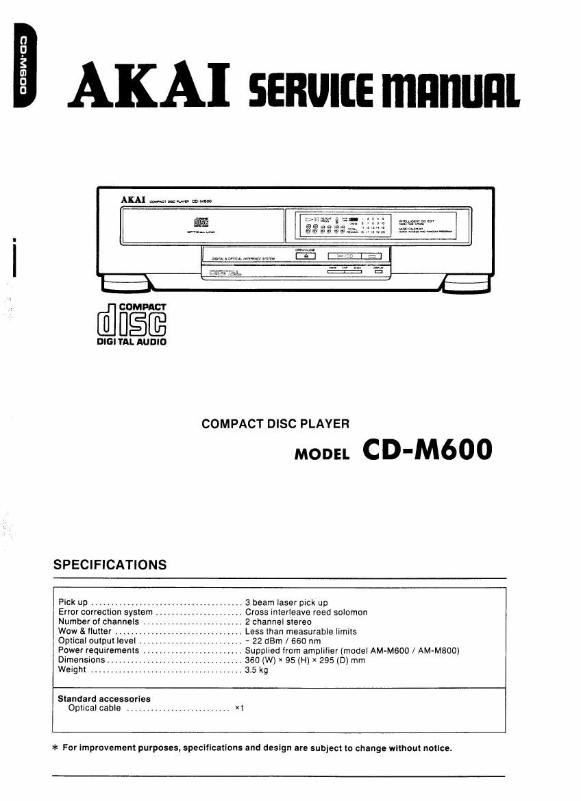
COMPACT DISC PLAYER
MODEL C D-M600
SPECIFICATIONS
Pick up ...................................... abeam laser pick up
..... Cross interleave reed solomon
..... 2 channel stereo
....... Less than measurable limits
....... , 22 dBm / 660 nm
Power requirements ....... Supplied from amplifier (model AM-M600 / AM-MBOO)
Dimensions ................... 360 (W) X 95 (H) x 295 (D) mm
Weight ..................................... 3.5 kg
Error correction system . .
Number of channels .....
Wow & flutter ..........
Optical output level ...A
Standard accessories
Optical cable .......................... X1
>i< For improvement purposes, specifications and design are subject to change without notice.
Page 2
* SAFETY INSTRUCTIONS
PRECAUTIONS DURING SERVICING
1, Parts identified by the /L\ (*) symbol are critical for
safety Replace only with pans number specified.
2. in addition to safety, other parts and assemblies are
specified for conformance with such regulations as
those applying to spurious radiationt
These must also be replaced only with specified re-
placements
Examples: RF converters, tuner units, antenna selector
switches, FtF cables, noise blocking capacitors, noise
blocking filters, etc,
3 Use specified internal wiring. Note especially:
1) Wires covered with PVC tubing
2) Double insulated wires
3) High voltage leads
4, Use specified insulating materials for hazardous live
parts. Note especially:
1) Insulation Tape
2) PVC tubing
3) Spacers (Insulating Barriers)
4) insulation sheets for transistors
5) Plastic screws for fixing microswitch (especially in
turntable)
5. When replacing AC primary side components (trans-
formers, power cords, noise blocking capacitors, etc),
wrap ends of wires securely about the terminals before
soldering.
semiarid?
6, Observe that wires do not contact heat producing parts
(heatsinks, oxide metal film resistors. fusible resistors,
etc).
SERVICE MANUAL
7. Check that replaced wires do not contact sharp edged
or pointed parts.
8. Also check areas surrounding repaired locations.
9. Use care that foreign objects (screws, solder droplets,
etc) do not remain inside the set.
Page 8
V. PARTS LIST
ATTENTION
1.RECOMMENDED SPARE PARTS
We suggest you to stock the lollowing Recommended
2. CD MECHANISM
MLND. Part no.
Description
1- When placing a" order tor part5. be sure to list Part Noe Model No. and the description at eachpxrt. Spare Part items listed below since they can cover i m-saossw cmsss new oursEfiT mm
Otherwise, the non-delivery of the part or the delivery at a wrong part may result. most a, the routine service. g 52:22;ng 21$? Kss-zioA
2. Please make sure that Part No. Is correct when ordering. 3 78372237 SC Moron SFINDLE PART
It not, a part dlflerent from the one you ordered may be delivered. mute. Pan No. Dose-1mm 7 Swag?) gagioégzzsgiéccxr
3. since the parts shown In Parts List or Prelinnnary Servlce Manuel may have been the abject or changes, , suaazam sc MOTOR Lemme Pom : eM-eazaui 5,; MOTOR Lmfimg war
please use this Parts List Ior all Imure relerehce. 2 5"'537552 55 Mom SUDE PM to viz-3mm; GEAR wow WHEEL
9 94-53722 SC more SPINDLE m u EM»BJ71552 Sc Moron sLioE PART
. #504502 PICK UP Kss-etuA .2 EMS); 5w LEAF Mswei 555
5 $243351 9 LED SUI-322: RED ta 55-39mm sw LEAF sppezz (II--
5 7 2 D SILICON N l l 14 15-536455 eiozoxnasi-L cw
HOW TO USE THIS PARTS LIST 7 teeaaeamt osILicoN ISRISE-lDOHS FIG 5 153: Preazsxossri. cm
a Euqavuiu o zsnsn H stsea r25 5 MR-CHMS? J1 My GEM;
~ ~ _ a ED~JE7733J o ZENEFI H HZSECSL :05 7 3.35559w 5er LOADING
1. This Parts List VIISIS those parts which are considered necessary lor repairs. Other common 93:5. such as resis 0 E03873? DZENER H stsAzL F05 m Mzraaazm CAM GEAR LOAD;
tors and capacitors. are listed in the Common LlSI lor Sen/ice Parts lrom which these pans s ould be selected .1 9.33923 ic mm 9 25455391 flenaoxoasrL cmcouo
and stocked. 2 243343 {32:33:23 2a Mz-asa347 CLAMFER
v , - » - _ I3 '3 21 SZrflMSBJl HOLDER CLAMPER
2. The Recommended Spare Parts List shows these parts In the Parts List which are constdered particularly import Ei-sewew iccxonzsa 22 Zo-aseseiii 5P PUSH AMP
ant for service. is aoazzsu IC LC3517BS-IS 0° 23 50-352mm MSK W" 5 m
. - . i . - - . i to images; ic uwmszizA FXCDZ 2 2. 2.382635 HOLDER 01,54; 5,13)
3. Parts not shown in the Fans List and Common List lor Service Parts WIII not in principle be supplied. Bosnian 030 as csnzmowsanounz 25 2482687 HOLDER msc Sit-i
4. How to read the Parts List. in 3-381 no; use X'TAL HC-AQIU 199mm: 21! 25.365592 Sp puLL DISK mm
is sM-aaeteei IND FL Fipscvm W 27 3.317975 srowen aueeen
20 Es-aeeeo: sw LEAF Mew-i535 30 M24733, ANGLE my
a) Mecmmsm BIOCK b) PC Board 2| 554mm sw LEAF swezz 014 3. 15.4325 pmzsxosn cm
21 55-39451 sw ncr son-izshs ms
2. HEAD BASE BLOCK 6. MAIN PC BOAFID 23 9'3! murmurs
24 ET-35437I m DTCIZIES NOTE:
rut-Mo- PM no. Description mm. Pm No. no-urivuon :3 $3233: I: £33232 Parts will not be supplied it they are not listed in the
7 ET-294555J TR 25A|515 QR I l's ear on the essemblin illus-
i EH-TZOZIASZOA HEAD ruse BLOCK iCi El-GZASJE ic HDHMQBP is Er-aousu m 25.53,, cm par-s ' I even II "my app 9
2 NF-NZZUSAUIDA HEAD RIP Parent c icz emssam ic MBHBM-SBIM 2, 514,945 J n: 235.329 QR ms "31'0'15 Wlm relerence N0-
3 23477375 PANzoxoasrL cm CIA Ec-asaase c MMV v 223M new [uses] 30 5mm m gsczosn on ms
t 15-5354 mozo-unsn cm cia 53450949 c MMV v 223M 2500c [J] 3 57.3971an n: 2503330 astuy
g 2 «02395 5: cs ANGLE ADJUST CIC Ecrusasv c MMV v 229M 125AC [CA] 32 amass m 250mm
)0 EI-siaau osc X'TAL NC-IBC V 33 £123me In 2502005 on ms
t _ _ - :4 Er-asmci TH zsozow EF ms
SP (Service Parts) Classification 35 zwosuiw WIRE ASSY on59 I2?
. . . ' as MBJSSESNi BELT Lemme
This number corresponds with the Individ flrflfgfigzma'y ([ISIIlgiiIIIK I, )
ual artsin xnm rinthtfiure. * " ' 5""
p as u be a 9 [a] BEAB (England) [U] . U/T (Universe Area)
[C] CSA (Caneoai
[E] CEE (Europe) [V] > VDE (w. Germany)
[41 JPN (Janan) [Y] . Cusxom Version
SP (Serwce Parts) Classrtication
These reference symbols correspond
with component symbols in the
Schematic Diagrams
The available PC Board Stocks are listed separately.
5 When Part No. is known Parts Index at end 0' Parts List can be used to locate where that part is shown in Fans List
by its Reference No.listed at right of Part No,
WARNING
1h [*) INDICATES SAFETY CRITICAL COMPONENTS. FOB CONTINUED SAFETY. REPLACE SAFETY
CRITICAL COMPONENTS ONLY WITH MANUFACTURES RECOMMENDED PARTS.
AVEHTISSEMENT
.rlx [*) IL INDIOUE LES COMPDSANTS CRITIQUES DE SECURITE. FOUR MAINTENIR LE DEGRE DE
SECURITEDE LAPPAREIL, NE HEMPLACER OUE DES PIECES HECOMMANDE' PAR LE
FABRICANT.
um usr