Akai CDM 1200 Service Manual
This is the 34 pages manual for Akai CDM 1200 Service Manual.
Read or download the pdf for free.
If you want to contribute, please mail your pdfs to info@audioservicemanuals.com.

Extracted text from Akai CDM 1200 Service Manual (Ocr-read)
Page 1
UUZlW'CD
AKAI SEBUltEmlllllllll
AIM (mum-mm rum mum
Emmmmmm
©l
Iii
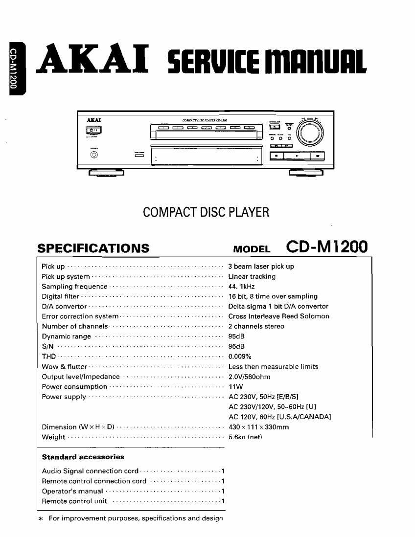
COMPACT DISC PLAYER
SPECIFICATIONS MODEL CD-M i 200
Pick up .............................................. 3 beam laser pick up
Pick up system ....................................... Linear tracking
Sampling frequence .................................. 44_ "(HZ
Digital filter ------------------------------------------ 16 bit, 8 time over sampling
D/A converter ---------------------------------------- Delta sigma 1 bit D/A converter
Error correction system ----------------------------- Cross lnterleave Reed Solomon
Number oi channels ---------------------------------- 2 channels stereo
Dynamic range ...................................... 95dB
- A 96dB
THD ................................................. 0009%
Wow & flutter ------------------------------------- Less then measurable limits
Output level/Impedance ----------------------------- 2.0V/5600hm
Power consumption -------------------------------- 11W
Power supply ....................................... AC 230V, 50Hz IElB/SI
AC 230V/120V, 50~60Hz [U]
AC 120V, 60Hz [U.S.NCANADA]
Dimension (WxHxDl -------------------------------- 430x111><330mrn
Weigh .............................................. 57510.1("ng
Standard accessories
Audio Signal connection cord ------------------------ 1
Remote control connection cord --------------------- 1
Operator's manual .......................... , AAAAA , ,1
Remote COHUOI unit ................................ 1
* For improvement purposes, specifications and design
Page 2
CONTENTS
SAFETY INSTRUCTIONS ....................................................... 3
DISASSEMBLY ................................................................ 5
PRINCIPAL PARTS LOCATION ................................................... 5
IC PIN FUNCTION .............................................................. 7
WIRING DIAGRAM ............................................................ 17
BLOCK DIAGRAM ............................................................. 19
SCHEMATIC DIAGRAM ........................................................ 21
PRINTED CIRCUIT BOARDS ................................................... 25
EXPLODED VIEW ............................................................. 29
MECHANISM ASS'Y .......................................................... 31
PARTS LIST .................................................................. 36