Akai CD 27 Service Manual
This is the 19 pages manual for Akai CD 27 Service Manual.
Read or download the pdf for free.
If you want to contribute, please mail your pdfs to info@audioservicemanuals.com.

Extracted text from Akai CD 27 Service Manual (Ocr-read)
Page 1
n
.0
r0
5'
w
u
KAI senmte mnnunt
E W'Eiiléé El M"
-. ._ as as u a
© © m- m m:
mum-CW CD ADVANCED WIEBPOLAINE DUAL D/A CONVERTER [lg]
l
1 \r J '-
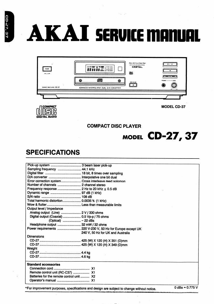
flcom-Afi MODEL CD-37
DIGI'IDASUDID
COMPACT DISC PLAYER
SPECIFICATIONS
moon CD-27, 37
Pick-up system .........
Sampling frequency .
Digital filter
D/A converter
Error correction system
Number of channels .
Frequency response .
Dynamic range ..
SIN ratio ........
Total harmonic distortion ..
Wow 8. flutter ....................
Output level / Impedance
Analog output (Line)
Digital output (Coaxial) ..
(Optical)
Headphone output ........ .
Power requirements ..........................
Dimensions
CD-27
CD-37
Weight
CD-27
CD-37
3 beam laser pickup
44.1 kHz
18 bit, 8 times over sampling
lnterpolative one bit dual
Cross interleave reed solomon
2 channel stereo
2 Hz to 20 kHz i 0.5 dB
97 dB (1 kHz)
103 dB
0.0035 % (1 kHz)
Less than measurable limits
...2V/3300hms
0.5 Vp-p I 75 ohms
- 22 st
32 mW I 32 ohms
220 V-230 V, 50 Hz for Europe except UK
240 V. 50 Hz for UK and Australia
425 (W) x 120 (H) x 351 (D)mm
425 (W) x 120 (H) x 349 (D)mm
4.4 kg
4.6 kg
Standard accessories
Connection cord .......................
Remote control unit (RC-637) .
Operators manual .....
Batteries for the remote control unit.
.. X1
'For improvement purposes, specifications and design are subject to change without notice.
0 st - 0.775 V
Page 2
*SAFETY INSTRUCTIONS
PRECAUTIONS DURING SERVICING
1 Parts indentllled by the i talc) symbol are crllical lor
satety. Replace only With parts nurnoer speciiied,
2 In addition to salety, other pans and assemblies are
spectlied lor conlormance With such regulations as
those applying to spurlous radiation
These must also be replaced only With specilied re-
placements.
Examples: RF converters, tuner units, antenna selecr
tor swnches. RF cables, noise blocking capacitors.
noise blocking liiiers, etc.
Use spectlled internal wrnhg Note especially
IJWIYES covered with PVC tubing
2) Double insulated Wires
3) High voltage leads
4 Use specilled insulating materials lnr hazardous live
pans. Note especially:
1) Insulation Tape
2) PVC tubing
3) Spacers (Insulating barriers)
4) Insulation sheets lor transistors
5) Plastic screws tor Iixing rnieroswirch (especially in
turntaole)
wnen replacing AC primary side components (trans
lormers, power cords. noise blocking capacitors, etc),
wrap ends ol wires securely about the termmals belore
soldering,
pineal?
6. Observe that wires do not Contact heat producing pans
(heatsinks. oxide metal Iilm reststcrs. IUSible resistors.
etc.)
7. Check that replaced Wires do not contact sharp edged
or painted pans.
8. Also oheck areas surrounding repaired locations,
9. Use care that lorelgri oblects (screws. solder droplets,
etc.) do not remain inslde the set.
u
or
SAFETY CHECK AI-I'ER SERVICING
Alter serViCihg, make measurements ol leakage-current
or resistance in order to determine that exposed pans are
acceptably insulated from the supply Circuit
The leakage-current measurement should be done he-
Iweeri accessible metal pans (such as chassis, ground
terminal, microphone jacks. signal input / output connec-
tors. etc) and the eanh ground through a resister or 1500
ohms paralleled With a 0.15 liF capaCitor. under the unit's
normal working conditions The leakagercurrent should
be less than 0.5 mA rrrts AC
The resistance measurement should be done between
accessible exposed metalparts and power cord plug prongs
With the power sWItch (ii included) ON" The resistance
should he more than 2.2 Mohrris
MAKE YOUR CONTRIBUTION TO PRO-
TECT THE ENVIRONMENT
Used batteries With the lSO symbol I0! recy»
cling as well as small accumulators (recharge- %&
able batteries). mini-batteries (cells) and starter
batteries should not be thrown Into the garbage can.
Please leave them at an appropriate depot, All other
household batteries can be thrown out Wllh the household
waste,
CLASS 1 LASER PRODUCT l
This product contains a low power laser device.
To ensure continued safety, do not remove any covers
or attempt to gain access to the inside oi the product.
Reler any servicrrig to qualified personnel.
Use actual size stickers
cuss i use: enonucr
truss: i usin PHODUKI
LUOKAN 1 LASER ulr:
KLASS 1 uses APPARAI
mwzsslt . luv-on 1mg;
-v SERViCE MANUAL
*INFORMATION
PRECAUTIONS IN REPAIRING
When repairing or adjustng the unit. pteae note the lollow-
ing points,
i Do not put excessiv pressure on the mechanical part
(operation pan), including the pick-up block, as ex-
tremely high mechanical premsinn is required in these
parts,
2. When the base is removed for repair or ad)ustment,
make sure that there are no metal oblects in the nar-
row gap between the P.C,board or the mecha pans
and the base.
. The Micro-Computer and the CD signal processing le
can be damaged by static electricity or leakage train a
soldering iron during repairing.
While soldering, please take the precautions against
leakage as in the illustration.
u
I GND
5
. Do not loosen any screws in the pickup block.
When handing the pick-up block. please reler to the
paints to NOTE when replacing the pick-up block.
.Keep salety lor hazardous invisible Laser Radiation,
DO NOT watch the Laser Beam (Objective lens) di-
rectly.
Models lor the some countries, laser warning labels
are atItxed on the unit and inside of the unit. as shown
below.
Read it caretully Ior your salety, when repairing or ad-
justan the unit.
at
F
SYMBOLS FOR PRIMARV DESTINATION
Primary destination at unlts are indicated wtth the loliowr
lng alphabet.
Symbols Principaiioestinarpns 7
[Bl _, UK,., , W
. EULQEe,tsxcem.UK)., ,
Australlaii
Germany ,
.7 universal 5r
l Custom version
SEHVtCE MANUAL