Aiwa AD F990 Service Manual
This is the 40 pages manual for Aiwa AD F990 Service Manual.
Read or download the pdf for free.
If you want to contribute, please mail your pdfs to info@audioservicemanuals.com.

Extracted text from Aiwa AD F990 Service Manual (Ocr-read)
Page 1
S/M Code No. 83-014
DATE OF ISSUE 5/1983
AIWA®
SERVICE MANUAL
MODEL NO.
STEREO CASSETTE
DECK D-FSSD
TYPE. H,HU,U,E,K,G
Follow the instructions carefully, which will allow the user to optimise the products'
performance and give many years of serivce.
1, No scratch and melting shall be made to covered lead-wires of an 6. General instructions for mechanism repair
34c. primary circuit including mains loads. 1) The heads, capstan and pinch roller shall be cleaned of good
2 No illogibility shall be given to the specification plate, the cam quality alcohol after repaired. because dirty heads shall cause
tion labels, the tune labels and others. distorted sounds while dlrty capstan and pinch roller shall
3. When, on pattern sides of circuit boards, additional repair-parts occur wow/flutter and take-up fault.
have been made up, the parts shall be firmly glued to circuit 2 Lubricants been stained the surfaces of transmitting portion
boards or other components, unless the parts can be attached or the belts, idlers, caDStan and pinch roller shall be removed
firmly. because slippery and faulty tape travel shall be caused.
4.The following matters shall be maintained a they are, when 3 When oiling, only one or two drops shall be applied so as
repairing. not to run over and be dispersed. Note should be taken of the
1) Soldering of leadwire ends
'Care should be taken of the space distance in an ac. pri-
mary circuit as well as soldering.
2) Wiring and holding of lead-wires with wirevclips and binders
3) Materials of leadwires
'e.g.; For UL models, leadwires to be used shall be ap-
proved or accepted by the UL.
4) Location of all kinds of insulators
5i Setting of voltage selector switch
'Set the Voltage Selector Switch to 240V, 220V, or 120V,
According to your Local Voltage.
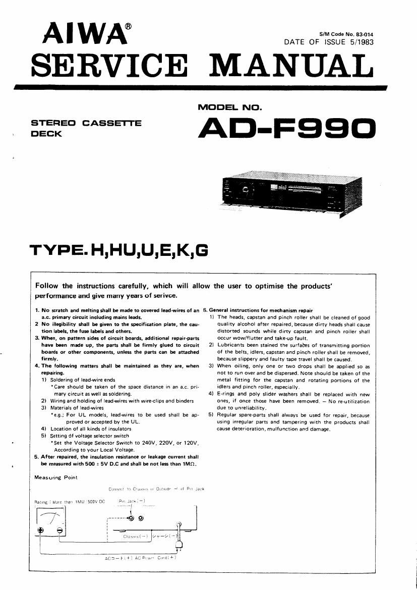
5. After repaired, the insulation resistance or leakage current shall
be measured with 500 2 5V D.C and shall be not less than 1MB.
Measuring Point
Cg'llli'lz '
«. m OlISlGr - ill Dil .a:~
metal fitting for the capstan and rotating portions of the
idlers and pinch roller, especially.
E-rings and poly slider washers shall be replaced With new
ones, if once those have been removed. - No re-utilization
due to unreliability.
5) Regular spare-parts shall always be used for repair, because
using irregular parts and tampering with the products shall
cause deterioration, multunction and damage.
4
Ralmg : More may» lMsz 'SGDV DC
Chasm.» l ~>
Ac:-i.+) AC Di :.4 cumin»;
Page 15
Pin No.
Pin mark
Function
OSC1
This pin supplies external operation
clock. Inputs the mechanism control
400 Hz.
®
0562
Internal clock oscillating pin attached
to the external resonance circit. Not
connected.
CI»
Compu~brain data output CAL a):
Set ta Hi when 2" bit is set.
C1
Compu-brain data output CAL '1:
Set to Hi when 2 bit is set.
C2
Oompu-brain data output CAL 2:
Set to Hi when 2 bit is set.
C3
Compu-brain data output CAL 3:
Set to Hi when 23 bit is set.
Compu brain data output CAL 4:
Set to Hi when 2 bit is set.
®®®®®®
El?
Comm-brain data output E0 $2
Set to Hi when 2° bit is set.
E1
Compu-brain data output E01:
Set to Hi when 2 bit is set.
EZ
Compu-brain data output E0 2:
Set to Hi when 2 bit is set.
E3
Compubram data output E0 3:
Set to Hi when 23 bit is set:
E4
Compu-brain data output E0 4:
Set to Hi when 2 on is set.
®®®®®
MEG ¢v
Set to Hi when 30.31.32, 83, B4 of
the data are set to wow dUring bias
adjustment.
To change recording equalizer.
MEQI
Set to Hi when BO, 51.32.53.321 of
the data are set to 1111! during bias
adjustment.
To change recording equalizer.
HOLD
HOLD mode demand input Din.
@®
INT
Interruption demand input pin. Not
connected.
VDD
Power pin. Connected to the backup
capacitor circuit. Approx. 5.3V in
general. Approx. 5.6V just after
power OFF,and then gradually drops
in several hours.
K
Compuhrain key. CompuAbrain start/
K-CST
For cassette detection. Set to Hi
15
reset when this is set to L0.
when a cassette is present.
Page 22
3-1-2. Pin function |C5V
This is the attenuation quantity UP/DOWN control oscillator,
and the UP/DOWN speed is determined by its time constant.
Pin No. Mark Function Remarks
2 ROUY, 10 sttep attenuator outputs L, R Symmetry
15 LOUT, signal applied to IN is attenuated in 7 steps, 0 - Gods in
10 dB steps.
ouTl Q
3 R-IN, 10 dB-step attenuator inputs
14 LIN, INx
4 A-GND GND pins A-GND
13 -
INI
5 R-INz 2 dB-step attenuator inputs
12 L-IN, 0m-2 O
6 R-OUT2 2 dB-step attenuator outputs
11 L-OU'I', Signal applied to IN is attenuated in 5 steps, 0 - 8 dB in
2 dB steps.
7 INH INHIBIT pin
When this pin is set to "L", all input/output are shut offsetting
the INHIBIT mode.
(STATE HOLDINGI Normal operation in "H" level.
8 D00 Attenuation quantity indicator DC ourrent output,
Attenuation quantity 0 ~- on is classified into 13 steps and
current of approx. 50 uA/step is output.
50 wt 0 dB
R
550 uA
" Attenuation quantity can be made
symmetrical to the DC voltage by
w inserting a resistor between this
pin and GND.
. . . VDD
9 05¢ Oscillator CR. connection pin
22