Accuphase T 109 V Brochure
This is the 4 pages manual for Accuphase T 109 V Brochure.
Read or download the pdf for free.
If you want to contribute, please mail your pdfs to info@audioservicemanuals.com.

Extracted text from Accuphase T 109 V Brochure (Ocr-read)
Page 1
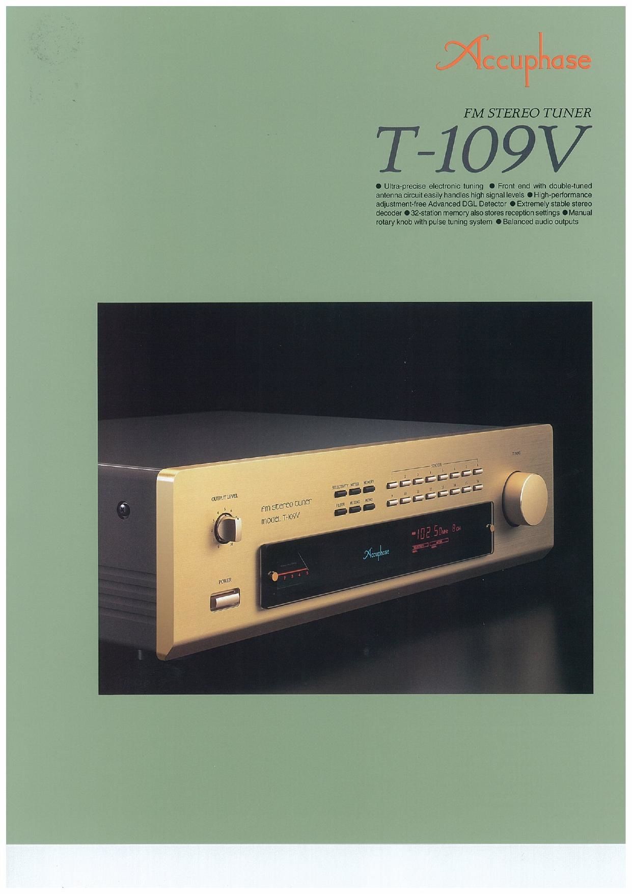
FM STEREO TUNER
T-109V
O Ultra-precise eleclronic tuning O From end with double-tuned
antenna circuit easily handles high signal levels 0 High-performance
adjustmem-lree Advanced DGL Detector 0 Extremely stable stereo
decoder O 32-slalion memory also stores reception settings 0 Manual
rolary knob with pulse tuning system 0 Balanced audio oulputs
Page 2
Among the great variety of program sources
available today, such as 005, MDs, and DVDs,
FM broadcasts still play a special role, since
they cover the entire spectrum from live perfor-
mances of time-honored classical works to the
latest hits. The FM band provides a rich choice
of music all day long.The FM tuner therefore is
an important component in a stereo system
designed to enlighten and entertain.
The FM Stereo Tuner T»109V from Accuphase
was conceived for the music lover who accepts
no compromises when it comes to sound qual-
ity. It is based on the highly renowned model T-
109, providing even further refined sonic char»
acteristics and performance. Externally, the front
panel has been redesigned to match the styl-
ing of recent Accuphase components. The PLL
electronic tuning system pulls in any desired
station with pin-point precision and total reliabil»
ity. A convenient memory function lets you store
as many as 32 stations including sensitivity and
filter on/off settings, and the pulse tuning prin-
ciple developed by Accuphase blends digital
accuracy with the familiar feeling of operating
an analog tuning knob, The front end employs
a dual»stage design that can handle even ex-
tremely high input signals without cross modu-
lation problems, and the Advanced DGL De-
tector assures high performance and rock-
stable reception.The stereo decoder takes so-
phisticated circuit topology to new heights, with
its reference frequency provided by a ceramic
resonator for utmost stability. To avoid diluting
the outstanding sonic virtues of this tuner fur-
ther down the signal path, a balanced output
stage sends the audio signal to the next com-
ponent without any sound quality deterioration.
A remote commander is also supplied, and the
champagne gold front panel blends perfectly
with any listening room.
Ultra-precise electronic tuning
The T-109V tunes to the station frequency by
means of a quartz crystal oscillator that oper-
ates with extreme precision and is virtually free
of time or temperature induced drift. It precisely
locks the tuner to the reception point that yields
minimum distortion and maximum sensitivity.
Electronic tuning also means that the T-109V is
not susceptible to modulation and other noise
caused by external vibrations.
Front end with dual-stage demodulator
handles high input signals easily
Each FM tuner has a front end that picks just
the desired station out of the crowded FM band
and convert the radio frequency into an inter-
mediate frequency. The design of this stage is
highly crucial, since it must discern and select
minute signals, while at the same time being
able to withstand the very high levels that can
occur when a strong station is broadcasting
nearby. Freedom from interference and distor-
tion is what makes the difference between a
run-of-the-mill product and a sophisticated high-
class FM tuner.
Rediscover the joy of music - with this top-flight FM stereo tuner
featuring advanced RF technology. The front end can handle even
extremely high input signals, the Advanced DGL Detector assures top-
quality reception performance, and the stereo decoder employs a ceramic
resonator for utmost stability. Pulse tuning recreates the ease and feel of
manual tuning in addition to the convenient 32 station memory.
Figure 1 shows the circuit diagram
of the front end employed in the T-
109V. Accuphase has long been ad-
vocating the "double-tuned antenna
circuit principle". whereby a high se»
lectivity circuit precedes the an.
tenna signal amplifier stage. This
prevents intermodulation distortion
and other undesirable side effects
which can occur if a strong signal
is amplified directly. The RF ampli-
fier stage uses FET devices con-
figured as a low-feedback cascode
Trix-iii
i.
To
lF AMPllllER
mum
mm
Ff
l
rim
MlCROPROCESSOR
t
.0... _t
m... a... _
Fig. 1 Circuit Diagram of Front-End
amplifier. The input
stage gate features a
PlN»diode attenuator
that is switched on or
off by a microproces-
sor, depending on the
antenna input level,
This assures high-
quality reception. free from interterence and dis»
tortion, even in areas close to strong broad-
cast stations that could otherwise overload the
front end.
wiue range
Delay circuit With 24 high speed was le assures a
(A) Principle of DGL Detector
Potnt @
of Fig. (A) , J. J Incoming signal
iu
T T l l
PW" @ - Del at +
0,ng ac , niri 3V 5'9"
Point to Excluswwn
or Flg. (A) output
High-Performance Advanced DGL Detector
Accuphase originally developed the DGL (Dif-
ferential Gain Linear) detector, featuring low dis»
torticn. high S/N ratio, low capture ratio, and re-
liable, adjustmentfree performance. For the T»
109V, Accuphase has urther developed and re-
fined the DGL principle, resulting in the Advanced
DGL Detector,
Figure 2 (A) shows the circuit principle of the
Advanced DGL Detector. The input stage uses
a high-speed comparator as a broadband 2.4
MHz amplifier to pre-
vent beat interference.
The delay circuit con-
sists of 24 high
Figure 2 (B) illustrates
the DGL operation
principle. The delay
circuit takes the slight
output delay of high-
speed logic ICs into
consideration. An ar-
rangement of 24 ICs
delays the phase
angle by 114 degrees
to assure minimum
distortion and maxi-
oigiial WIIIDilW Corner lullctlal'i
. output
y High-speed cMos IC\
Jot local exclustvc on I
fated, the excluslve-OR output © 5 equalr
ized and the lwpass tiller output IS o, 00 or Di.
When incoming signal ® is not demodlr ExclustvtzOR Gale OWNS WV"!
Signai to orm and closes with
(B) Operation Principle
Fig.2 Advanced DGL Detector
wrien the lncomtng signal is uoiriouutaieu. the exclusive-
oa output becomes uiioqualized accomiiig tattle oompios-
Stall ratio and the integral value ouiuui tioiii Iha lowpass
Itl|Erchanges iii the elec|llc ootaiilial (audio signalt as iiioi-
cated by the slaiitoa line.