This is the 4 pages manual for Accuphase PS 510 Brochure. Read or download the pdf for free.
If you want to contribute, please mail your pdfs to info@audioservicemanuals.com.
Page: 1 / 4
Extracted text from Accuphase PS 510 Brochure (Ocr-read)
Page 1
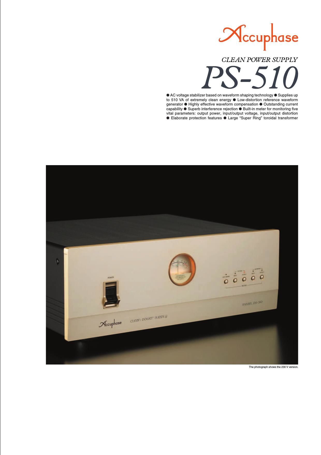
Tap into a totally clean source of AC energy for up to 510 VA -� Revolutionary
waveform shaping technology enables highly precise compensation,
creating a pure energy source of 230 V AC (or 120 V AC) ±2% with max.
0.22% THD. Connect audio or video equipment for a drastic improvement
in sound and picture quality. Monitor output power (VA), input/output
voltage (V), and input/output distortion (%) on the built-in meter.
The Clean Power Supply components from
Accuphase are revolutionary products that
remove noise and impurities from the AC power
line and improve signal quality by continually
monitoring and shaping the power supply
waveform. They have been widely acclaimed
for drastically improving the sound and picture
quality of audio and video equipment. The
PS-510 is an upgraded version that
incorporates latest MCS+ circuit topology in the
waveform compensation amplifier section. The
reference signal generator features further
improved accuracy to assure the lowest possible
distortion in the output waveform.
The PS-510 uses waveform shaping technology
to turn the power from a regular AC outlet into
a highly pure sine waveform for use as a stable
and uncontaminated energy source of A/V
components. To achieve this, the PS-510 takes
the power source waveform and compares it to
a highly accurate and stable reference
waveform. Based on this comparison, it then
adds or subtracts exactly the required amount
of correction. The compensation required by
this innovative technique typically is only a
fraction of overall power. The PS-510 therefore
operates with high efficiency and produces little
heat, allowing it to be designed as a fairly
compact and lightweight unit. Since all circuitry
is analog and there are no oscillators or
switches, the PS-510 itself does not act as a
source of spurious high-frequency noise.
0 10k 20k -100.0-75.0 -50.0 -25.00.0 [dB]
0 10k 20k -100.0-75.0
-50.0 -25.00.0 [dB]
50Hz
50Hz
[Hz] [Hz]
80
60
40
20800
600
400
200
0 100 200 300 400 500
0 100 200 300 400 500
[%]0.8
0.6
0.4
0.2 [VA] [%]Effi-
ciencyInput
power
Efficiency
Input/output powerTHD
Output power [VA]Output power [VA]
Line filterMeter selector
buttons
Alarm indication
circuit
Adding/sub-
tracting circuit
Error
detector
Wavefor m
comparator
Reference signal
generator Rectifier
Meter
AC
OUTPUTS
Waveform compensation
amplifier using "MCS+"
and "Current feedback"
circuitry
Power Supply Waveform and Clean PS-510 Output Waveform
Almost all electrical devices used in a household convert the AC supplied
by the outlet into a DC current for powering internal circuits. This task is
performed by a rectifier. As shown in photograph a, the rectifier load
current has a pulse waveform with a large current flowing momentarily in
the vicinity of the voltage peak.
This causes a voltage drop, resulting in clipping of the voltage waveform,
as shown in photograph b. A clipped waveform with a high amount of
distortion contains many unwanted frequency components, or harmonics,
as shown below. When entering the audio circuitry of an amplifier through
the power supply, such harmonic components can interfere with the audio
signal and cause intermodulation distortion which has a highly detrimental
effect on sound quality.
When passing through the PS-510, the deformed waveform is restored to
its original sine wave pattern (see frequency spectrum in the graph below).
The result is a clean sine waveform as shown in photograph c.
Frequency spectrum of power line
Frequency spectrum of power line (photo b)Frequency spectrum of PS-510 output
(photo c)
AC Voltage Stabilizer Based on Waveform Shaping
Technology
The PS-510 accepts AC power on the input side,
processes it using internal control circuitry,
and supplies it as clean AC power on the
output side. Most of the AC energy from the
input is carried over to the output. The loss
introduced by the PS-510 is very small,
since it consists only of the power required
for waveform compensation.
As shown in Figure 1, the signal from the
secondary winding S
1 of the transformer
reaches the adding/subtracting circuit and
appears at the output as output voltage
(e
0). The S 2 signal from the transformer goes
to the reference waveform generating circuitwhere it becomes a high-precision sine waveform (e
i)
synchronized to the input frequency of 50/60 Hz.
This reference sine wave (e
i) is then used as refer-
ence signal to be compared to the output voltage.The differential component is extracted and used by
the adding/subtracting circuit to provide exactly the
required amount of compensation for turning the out-
put into a high-precision sine waveform.
Highly Effective Interference Rejection
The input side of the PS-510 is equipped with a line
filter for removing any high-frequency noise
components present in the power line, such as
generated by digital equipment. The primary and
secondary windings of the power transformer are
kept totally separate, and the fully shielded design
shuts out any externally induced noise. Since the
amplifier uses the feedback principle, output
impedance is extremely low. This prevents any
possibility of mutual interference between components
connected to the outputs of the PS-510.
Built-in Meter Allows Monitoring of 5 Parameters:
Output Power, Input/Output Voltage, Input/Output
Distortion
The meter of the PS-510 lets the user see at a
glance how much power (VA) the connected equipment
is consuming at any given time. This is especially
helpful for components such as integrated amplifiers
or power amplifiers whose power consumption differs
considerably depending on the volume setting and
actual music signal. When the maximum rated output
power of 510 VA is exceeded, the meter illumination
flashes as a warning indication.
Fig. 1 Operation Block Diagram of PS-510
Output power/input power (efficiency)
characteristicsOutput power/THD characteristics
Fig. 2 PS-510 Load Characteristics
Assembly with input voltage/
distortion monitoring circuitry Meter of 230 V AC version
Photo a Current waveform of rectified load
Photo b Voltage waveform of AC line (distortion approx. 3%)
Photo c PS-510 output waveform
(distortion approx. 0.2%)
Load: purely resistive Load: purely resistive
Page 2
14.1 V 14.1 V
+170/
325 V
+14.1 V
00
-170/
325 V
-14.1 V
t
t
14.1 V 14.1 V
+170/
325 V
+14.1 V
0 0
-170/
325 V
-14.1 V
t
t
[50Hz]
[60Hz]
From
secondary
winding of
power
transformerSquare wave
generator
Bandpass
filter
Bandpass
filterBandpass
filter
Reference
output
waveform
PS-510
230/120 V AC
output waveform
220/110 V
AC input
waveform
Compensation
waveformCompensation
waveform
PS-510
230/120 V
AC output
waveform240/130 V
AC input
waveform
Band-
eliminate
filter
Band-
eliminate
filter
Excellent Current Capability The power amplifier which performs waveform compensation uses the current feedback principle
for excellent high-frequency phase characteristics and operation stability. This is combined with
the MCS+ circuit renowned for superior performance and sound quality. The output stage uses
10 transistors rated for a maximum current of 15 amperes. These devices are connected in a
parallel complementary push-pull arrangement which boasts a rated output current of
2.2 A (4.2 A) and an instantaneous peak current (inrush current) rating of 30 A (60 A). This
demonstrates the excellent current capability of the PS-510.
-�� Assembly with 10 parallel push-pull
power transistors mounted to two
large heat sinks, waveform
compensation amplifier for
addition/subtraction, etc.
Compensation Amplifier Based on High-Precision Reference Signal Creates Pure 230 V (or 120 V) AC Source
-�� -��-�� -��
-��Low-Distortion Reference Signal GeneratorThe waveform of the signal detected at the S 2 winding of the power transformer (see
Fig. 1) is used by a highly precise Zener diode circuit to generate a square waveform.
A newly developed 50/60 Hz bandpass filter and band-eliminate filter is then applied
to the waveform. The filter
frequency is switched in sync with
the input frequency, for automatic
50 Hz and 60 Hz support. By routing
the signal through another
bandpass filter, a low-distortion
sine wave (reference signal) is
created that is not dependent on
the input voltage.
Note: The explanation is for the 230 V AC version of the PS-510. Figures in brackets refer to the 120 V AC version.
-�� -�� -�� -��
-�� Assembly with reference signal generator and other circuitry
-�� -��-�� -��
-��Superior Waveform Compensating PowerWhen the input voltage is 220 V (110 V), the voltage at the secondary side of the transformer will also
be 220 V (110 V). To bring this to 230 V (120 V), 10 volts must be added, as shown in Figure (a).
Conversely, if the input is 240 V (130 V), 10 volts must be subtracted to yield 230 V (120 V), as shown
in Figure (b). (As the figures show, in actual operation, the peak value of 10 V, namely 14.1 V, is added
or subtracted.) The sine wave (e
i) synchronized to the input frequency and the output voltage (e 0) are
compared, and for any excessive or missing component, a compensation waveform up to a maximum
of ±10 V (peak value
±14.1 V) is generated
and imposed on the
output voltage. Con-
sequently, for an input
voltage range of 200-
253 V AC (108-132 V
AC) at the rated load
of 510 VA , the output
voltage is kept con-
stant at 230 V ±2%
(120 V ±2 %), with a
maximum distortion
ratio of 0.22%. These
values demonstrate
the outstanding wave-
form compensation
ability of the PS-510.
Waveform Shaping Principle of PS-510
(a) If power source voltage is
lower than 230 V (120 V),
addition is performed(b) If power source voltage is
higher than 230 V (120 V),
subtraction is performed
Reference Signal Generator Block Diagram
The photograph shows
the 230 V version.