Accuphase PS 1200 Brochure
This is the 4 pages manual for Accuphase PS 1200 Brochure.
Read or download the pdf for free.
If you want to contribute, please mail your pdfs to info@audioservicemanuals.com.

Extracted text from Accuphase PS 1200 Brochure (Ocr-read)
Page 1
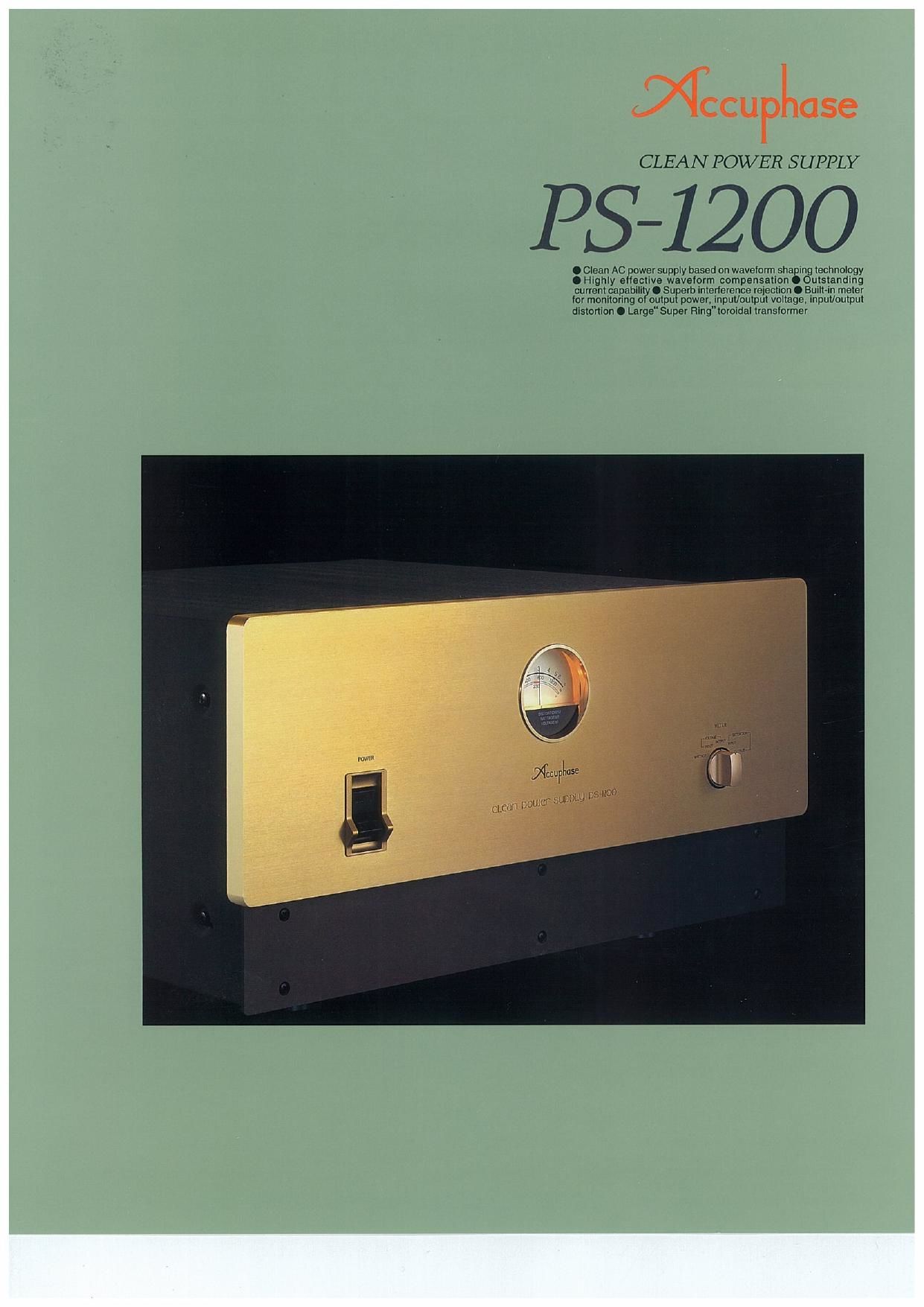
CLEAN POWER SUPPLY
5-1200
.Clean AC wersupply based on wavelorm shaping technology
0 Highly 9 (active waveform Compensation 0 Outstanding
current capability O Surem interference rejection 0 Built-in meter
tor monitoring 0 out u power, input/output voltage. input/output
distortion 0 Large"Super Ring"toroidal translormer
Page 2
The Clean Power Supply PS-1200 is a highrpower
version of the renowned PS-SOO. [t can deliver up
to 1200 VA which is more than ample to cover the
requirements of most high-quality systems. The
P871200 is based on waveform shaping, a revolu»
tionary technique that drastically improves the
purity of the AC power going into an audio sys-
tem.
Power Supply Waveform !
The power generated by the power plant origi-
nally is fed into the electrical grid with a clean
sine waveform. However, when power is with-
drawn from the local
AC outlet, the wave-
form almost invari-
ably is clipped. The
reason for this phe-
nomenon lies in the
electrical appliances
used in the house-
hold, Conventional
TV sets, personal
computers, audio
components, as well
as many other appli-
ances convert AC in-
put into a DC current
for powering the in-
ternal circuits. This zmfifinfugfrgmzmm5%
task is performed by
a rectifier consisting
of a diode and ca-
pacitor arrangement,
As shown in photo-
graph (a), the rectifier
load current has a
pulse waveform. In Photo (0) Output wavelorm oi
the vicinity of the P571200 (distortion: approx. 0.2%)
voltage peak of the sinus waveform, a large cur~
rent flows momentarily which causes a volt~
age drop, or in other words a clipping of the
voltage waveform, as shown in photograph (b).
A clipped waveform with a high amount of dis-
tortion contains many unwanted frequency
components, or harmonics. When entering the
audio circuitry of an amplifier through the power
supply, such harmonic components can inter-
fere with the audio signal and cause
intermodulation distortion which has a highly
detrimental effect on sound quality.
When passing through the PS-1200, the de-
formed waveform is restored to its original sine
wave pattern, as shown in photograph (c).
Photo (at Current waveform of
rectified load
The AC power lines in homes as well as in office
buildings, recording studios, and elsewhere are
also connected to equipment containing digital cir-
cuits and microprocessors, such as computers and
many kinds of electrical appliances. Highrfre-
quency noise components originating in such
equipment can enter audio components via the
power supply and severely affect sound quality by
causing intermodulation noise and distortion Only
when such noise interference is removed and to-
tally clean power is supplied, do audio components
become able to develop their full potential. Con-
sequently, upgrading the quality of the AC power
source of an audio system results in a sound quality
improvement that must be heard to be believed.
The Fs-1200 incorporates a revolutionary new
technique which constantly monitors the input
voltage waveform and adds or subtracts exactly
the required amount of compensation to achieve
a perfectly regular, sinusoidal waveform. This al-
lows it to supply up to 1200 VA of extremely stable
and clean energy to the components of an audio
system. Of course, the PS~1200 also has the abil»
ity to completely block any high-frequency noise
components, resulting in total absence of modu-
lation noise.
AC Voltage Stabilizer Based on Waveform
Shaping Technology
The PS-1200 accepts AC power on the input side,
processes it by comparing it to a precise refer-
ence waveform, and supplies it as clean AC power
on the output side. Most of the AC energy from
the input is carried over to the output. The loss
introduced by the PS-1200 is very small. since it
consists only of the power required for waveform
compensation. Compared to conventional AC volt-
age stabilizers, efficiency is much higher and ex-
cess thermal energy is low, allowing the unit to be
made relatively small and lightweight. Since the
power supply frequency is synchronized to the in-
put, an internal oscillator is not required, There-
fore the unit itself does not generate any
high-frequency noise.
Figure 1 shows the circuit diagram of the unit. The
signal from the secondary winding Sr of the trans-
former is routed through the adding/subtracting
circuit and appears at the output as output volt-
age (eu). The 82 signal from the transformer is sup-
plied to the reference waveform generating circuit
where it is turned into the high-precision sine wave-
form (er) synchronized to the input frequency. This
sine wave signal is then routed to the waveform
Tap into a totally clean source of AC energy, providing up to 1200 VA.
Revolutionary waveform shaping technology compares the AC input to an
ideal sine waveform and provides highly precise compensation. High-
frequency interference components are reliably removed, for further im-
proved sound quality and video image purity. A built-in meter allows moni-
toring of output power, input/output voltage, and input/output distortion.
comparator to
r.
be used as refer- 373;»- m m
ence signal. By _ I: , M
comparing the
output voltage "
(e..) to this refer» .
ence sine wave-
form (er), the
differential com-
ponent is de- ' u W .. .. 43-41:)
tected, Based on Output voltage/efficiency vs, input vollags
this information,
the adding/sub- '37
tracting circuit
can provide ex-
actly the re- _,
quired amount of
compensation
for turning the V
output into a 5'45
high-precision OutputvoltagevsJHD
sine waveform. Fig, 2 PS-1200 load characteristics
um um
Superior Waveform Compensating Power
Generally speaking, if the input voltage is for ex-
ample 110V/220V, 10 volts must be added to bring
mov AC mlwl mom.
m. .rrwr 10v
12%! HIV 395V linvacmw
WM,
/
x-wrc mm
m. W.
0 MW. i n mm |
,rrwr uiv my, ,
my azsv nw
rm. cmw;
mm : Mm
.rm .riw
n | n
.uiv my
mm rum at v mmpensuinninfldrd lhtwmn rm. r. W, rm IDDV, mm
mug. rs mum
Fig. 3 Fs-1200 waveform shaping principle
Meier selector
Adder/subilncler
a, lit-frat
®
Line filler
Reamer
Synchronized reference
waveform generator
Fig, 1 PS»1200 operation block diagram