Accuphase P 700 Brochure
This is the 4 pages manual for Accuphase P 700 Brochure.
Read or download the pdf for free.
If you want to contribute, please mail your pdfs to info@audioservicemanuals.com.

Extracted text from Accuphase P 700 Brochure (Ocr-read)
Page 1
MECUPLOSC
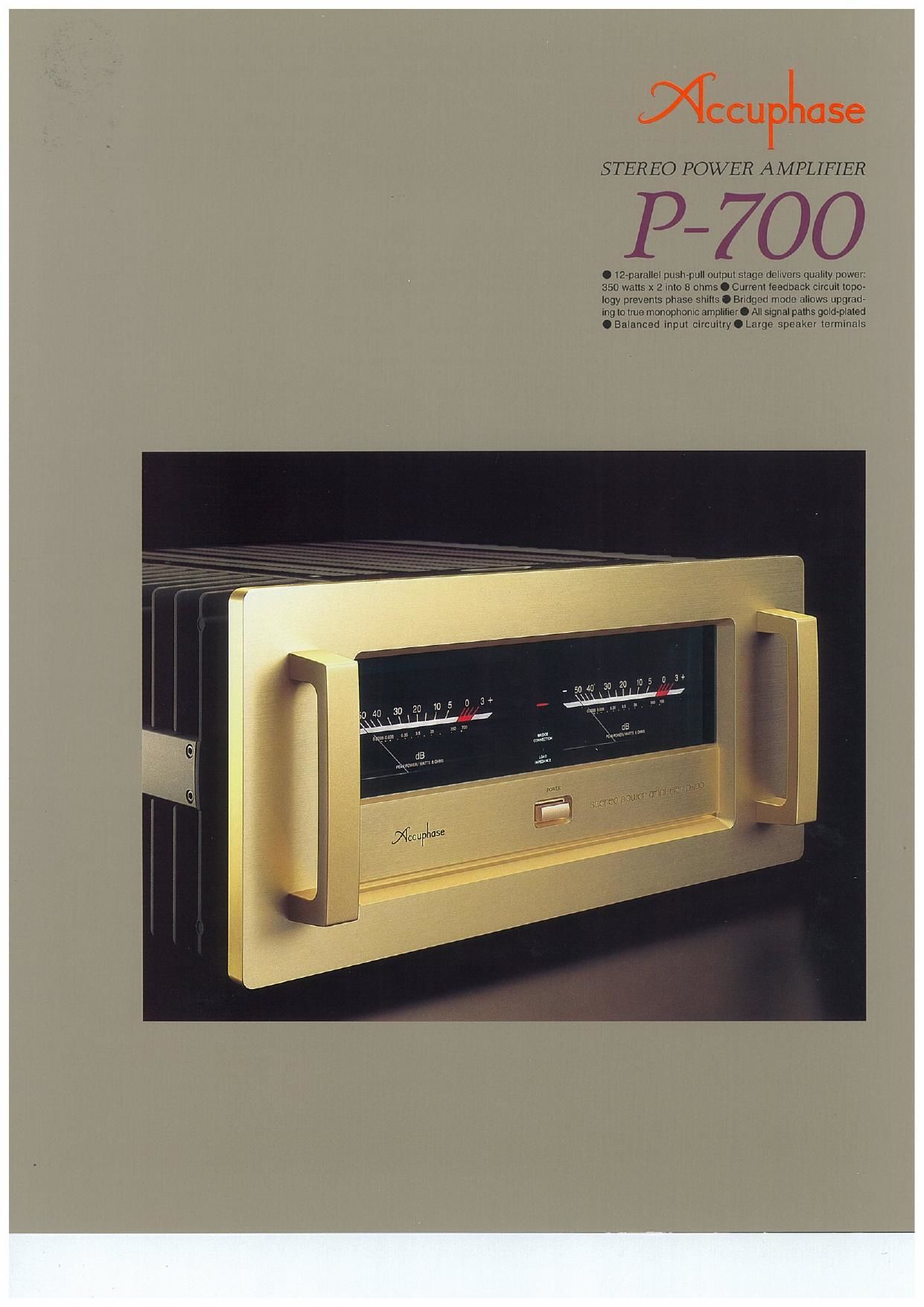
STEREO POWER AMPLIFIER
P-700
.12-parallelpush-pulloutput stage delivers quallty power
350 watts x 2 Into 8 ohms C Current ieedback circuit topo~
Ingy prevents phase shllls O Bridged mode aliows upgrad-
Ing to true monophonic amplifier 0 All signal paths gold-plated
.Balanced Input circuitryOLarge speaker termlnals
Page 2
The stereo power amplifier P~700 represents the
entire spectrum of Accuphase audio technology. It
has been designed to meet the strictest demands
of discerning audiophiles who will accept nothing
but the best. Top-quality parts and meticulous at-
tention to every detail result in a product that is
simply stunning in its musical accuracy.
For faithful reproduction of high-quality digital
sources, an amplifier must be able to handle ex-
tremely delicate low-level signals and thunderous
high-impact peaks with equal aplomb. It should not
be affected by fluctuations in speaker load, and
operation should remain stable at all times. The
P-700 perfectly fulfills all of these requirements.
Even difficult speakers that present not only a re-
sistive but also a reactive load to the amplifier can
be driven with ease and authority. In the output
stage, a total of twelve multi-emitter type wide-range
power transistors are arranged in a push-pull con~
figuration, resulting in impressive output ratings. By
using the P-700 as a monaural amplifier in bridged
mode, even higher output can be achieved.
The amplifying circuitry of the P-7DO features the
current feedback principle which combines superb
sonic qualities with extraordinary stability of opera-
tion and excellent frequency response characteris-
tics. This circuit requires only minimal phase
compensation in the high frequency range, and NFB
can be kept desirably low. The audible result is dras-
tically improved transient response.
In the power supply section. which acts as the
energy source for the amplifier, a high-efficiency
"Super Ring" toroidal transformer is used. in com-
bination with large filtering capacitors. This gives
the P-700 ample performance margins to handle
even the most severe demands. Balanced inputs
make the amplifier impervious against externally
induced noise during signal transmission. Gold plat-
ing of all major parts which carry the music signal,
including circuit board copper traces and input and
output connectors is another example of the P-700's
dedication to musical purity.
The large heat sinks protruding on both sides of
the amplifierand the panels of 15 mm thick extruded
aluminum with champagne-gold alumite finish make
A new reference for power amplifier excellence: the symbiosis of
sheer dynamic impact with subtle musicality. Current feedback
principle assures rock-stable operation. Multi-emitter power tran-
sistors in a 12-parallel push-pull configuration deliver 350 watts
per stereo channel into 8 ohms, or a full 1,000 watts into 8 ohms
during monophonic operation.
the P-700 a feast not only to the ear but to the eye
as well. This new reference model exudes an atmos-
phere of sheer competence and beautiful sophisti-
cation which is fully borne out in the music as heard
through this masterpiece. This is pure audio at its
best.
Modular power units in 12-parallel push-pull con-
figuration deliver ample muscle: 350 watts/ch.
into 2 ohms, 500 watts/ch. into 4 ohms, 350 watty
ch. into 8 ohms
The output stage uses multi-emitter type power tran»
sistors with extraordinarily wide and flat frequency
response. These devices also have excellent linear-
ity of forward-current transfer ratio and outstand-
ing switching characteristics. The transistors are
arranged in a 12-parallel push-pull configuration (see
Figure 1) and mounted on a massive heat sink made
from diecast aluminum. This assures effective heat
dissipation and yields impressive output capability
on the order of 350 watts per channel into two ohms,
500 watts per channel into four ohms and 350 watts
into eight ohms. The amplifier can drive even diffi-
cult reactive low-impedance speaker loads with
ease. The driver stage uses MOS-FET devices with
negative temperature coefficient, which cancel out
the positive temperature coefficient of the bipolar
power transistors, to guarantee perfectly stable
operation.
Current feedback circuit topology prevents
phase shifts
When the gain of an amplifying circuit increases,
frequency response, i.e. the bandwidth that can be
handled by the amplifier. becomes more narrow.
To counter this effect, a commonly employed
Fig. 1 circuit Diagram of the Amplifier Unit (one channel)
technique called
negative feed-
back (NFB) routes
pan of the output
signal back to the
input. If phase
shift is disre»
garded, a circuit "1-
designed to have 9 fifiwmlwmmtfm
high open-loop-
gain can apply a high amount of NFB, resulting in
the wide frequency response of a closed-loop
circuit. as shown in Figure 2.
Gnln _
Conventional amplifiers employ voltage NFB,
whereby the output voltage is used for the feed-
back loop. In the P»7OO however, the signal current
ratherthan the voltage is used for feedback. Figure
3 shows the operating principle of this circuit. At
the sensing point of the feedback loop, the imped-
ance is kept low and current detection is performed.
Current amplifiel
Power .
_ Inpui an, v ampilflar
or...
Buffer _c B
Fig. 3 Principle of current ludblck amplifier
Tmnu~impodnnca
. Inpu
An impedance-converting amplifierthen transforms
the current into a voltage to be used as the feed-
back signal. Since the impedance at the current
feedback point (current adder in Figure 3) is very
low, there is almost no phase shift. Phase compen-
sation can be kept to a minimum, resulting in ex-
cellent transient response and superb sonic
transparency with
natural energy
distribution.
an" a.
Figure 4 shows
frequency re-
sponse for differ-
ent gain settings
of the current
feedback ampli-
fier. The graphs demonstratethat response remains
uniform over a wide range.
Frlquency A-~
Fig i Frequency rum-swim «monument
WWW. mm mama
Bridged mode creates a true monophonic
amplifier with 1.000 watts into 8 ohms
Bridged mode means that the two channels of an
amplifier are driven with the same signal voltage
but with opposite phase. and their output is com-
bined. The P-700 provides a switch arrangement
for bridged operation, which turns the unit into a
high-grade monaural amplifier capable of deliver»
ing an awesome 70[) watts into 4 ohms and 1,000
watts into 8 ohms.
LOAD IMPEDANCE switch allows problem-free
driving of loads as low as 2 ohms
When driving low-impedance loads to high levels,
the LOAD IMPEDANCE switch can be set to "L0