Accuphase P 650 Brochure
This is the 4 pages manual for Accuphase P 650 Brochure.
Read or download the pdf for free.
If you want to contribute, please mail your pdfs to info@audioservicemanuals.com.

Extracted text from Accuphase P 650 Brochure (Ocr-read)
Page 2
Accuphase power amplifiers are designed to
realize two major goals: very low output
impedance (Note 1). and constant drive voltage
(Note 2). As a result. Accuphase amplifiers are
capable at driving any kind of speaker load with
optimum results, which is one of the reasons
behind the high praise that these products
invariably receive. The low impedance not only
ensures accurate speaker drive but also absorbs
the countereiectromotive force generated by the
voice coil. thereby eliminating a major source of
intermodulation distortion. The overall result is a
significant improvement in sound quality.
The P4350 is a stereo power amplifier which fully
implements these advanced circuit design
principles. Using only strictly selected high-quality
parts. this product was designed with a full
mastery of all aspects of amplifier performance.
The output uses six pairs of high-powertransistors
in each channel, arranged in a parallel push-pull
configuration These devices are mounted to
massive heat sinks located on both sides of the
unit. for efficient dissipation of thermal energy.
Power linearity is maintained down to extremely
low load impedances. This allows the amplifier to
easily drive even speakers with very low
impedance or uneven impedance curves, By using
the P-650 in bridged mode. you can create a mono
amplifier with even more impressive power
reserves.
Current feedback topology combines total
operation stability with excellent frequency
response. while requiring only minimal amounts
of negative feedback, The printed circuit boards
of the P-650 are made of a Teflon material with
extremely low dielectric constant and low loss.
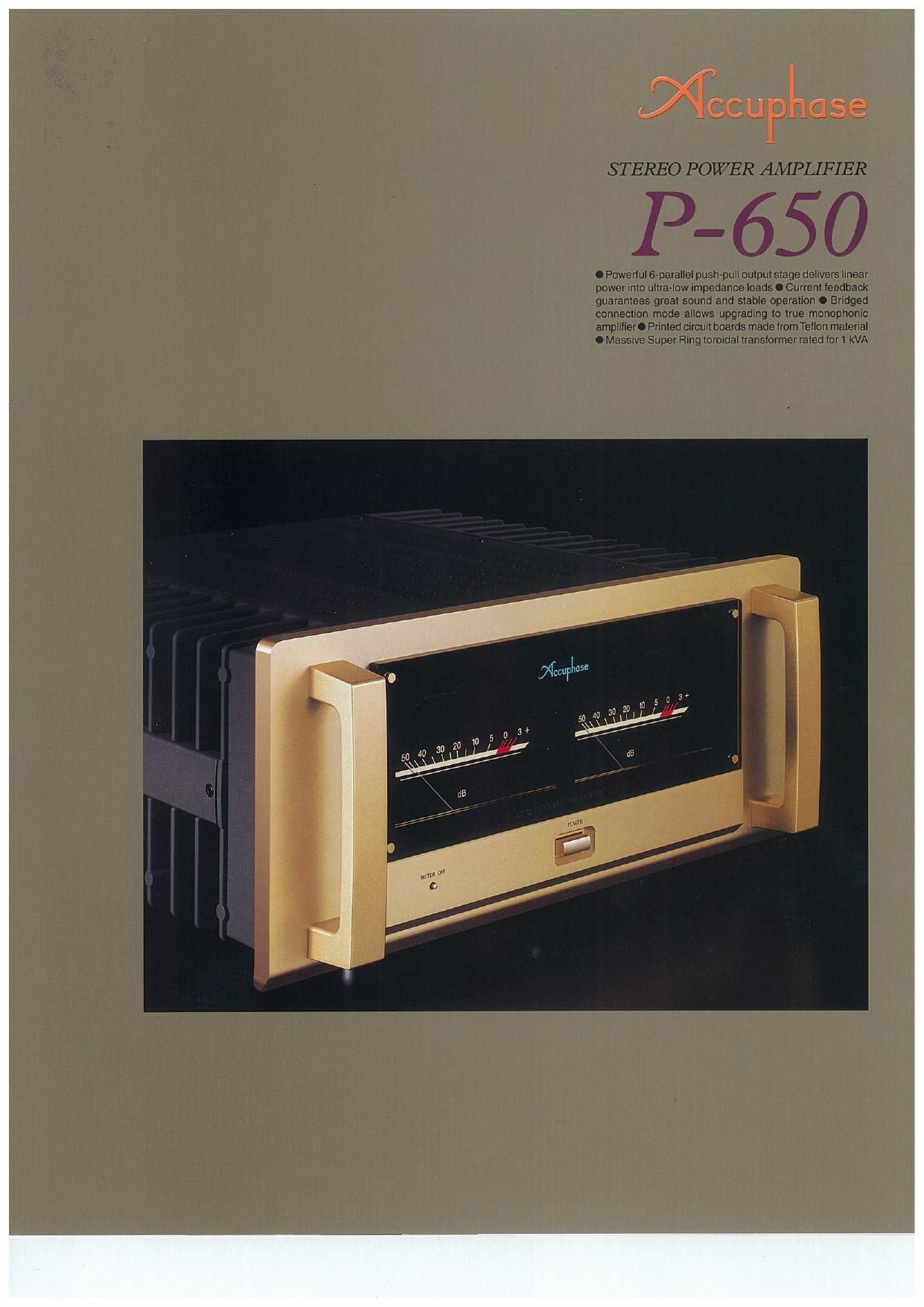
resulting in more transparent sound. The front
panel in traditional champagne gold features two
large analog power meters. The elegant and
sophisticated appearance of the amplifier will
enhance every listening room.
Astounding energy emerging from perfect poise - witness a stereo power
amplifier capable of delivering 720 watts (actual measurement) into 1-
ohm loads. Massive power supply with 1000 VA toroidal transformer
and wide-band high-power transistors in 6-parallel push-pull
configuration ensure constant-voltage drive. Teflon printed circuit
boards feature low dielectric constant and low loss. Current feedback
topology guarantees stable operation up to ultra high frequencies.
Note 1: Low amplifier output impedance
The load of a power amplifier. namely the loudspeaker generates a
counterelectromotive force that can flow back into the amplifier via the NF
loop. This phenomenon is influenced by fluctuations in speaker impedance.
and interferes with the drive performance of the amplifier.The output impedance
of a power amplifier should therefore be made as low as possible by using
output devices with high current capability.
Note 2: Constant drive voltage principle
Even in the presence of a load with wildly fluctuating impedance. the ideal
power amplifier should deliver a constant voltage signal to the load. When the
supplied voltage remains constant for any impedance, output power will be
inversely proportional to the impedance of the load. A conventional amplifier
can be easily made to operate in this way down to a load impedance of about
4 ohms. However. at 2 ohms and below. much more substantial output reserves
are needed. which can only be sustained by an extremely well designed and
capable output stage and a highly robust and powerful power supply section.
To build such an amplifier is a task that requires not only considerable
experience and resources but also a thorough reappraisal of basic tenets.
Power units with 6-parallel push-pull
configuration deliver ample linear power: 400
watts into 2 ohms, 200 watts into 4 ohms. or
100 watts into 8 ohms
-_
The output stage uses high power transistors with
excellent linearity and switching characteristics.
rated for a collector dissipation of 130 watts and
collector current of 15 amperestThese transistors
are arranged in a 6-parallel push-pull configuration
(Figure 1) and mounted on massive heat sinks
made from diecast aluminum, for efficient heat
dissipation.This enables the P-650 to effortlessly
drive even speakers with extremely low impedance
or with reactive loads
Figure 2 shows the output/voltage characteristics
at various load impedances. It can be seen that
output voltage remains nearly constant regardless
o I u u :2 Au u
' Wm
WW 0) -
Figure 2 Load Impedance v1. output pwnr
(mitpiit voltage/outlaw ounanl) of P»650
of load. which means that output current increases
linearly. The actually measured clipping power is
an impressive 720 watts into 1 ohm. 518 watts
into 2 ohms, 320 watts into 4 ohms. or 178 watts
into 8 ohms
Current feedback circuit topology prevents
phase shifts
-
The P-650 employs the so-called current leedback
principle. Figure 3 shows the operating principle
of this circuit. At the sensing point of the feedback
loop. the impedance is kept low and current
Currant
- Input adder
.... r---p .
Trans-int mm.
I n put amp lllor
'
network
Figure 3 Principle of current feedback amplifier
detection is performed. An impedance-converting
amplifier then converts the current into a voltage
to be used as the feedback signal. Since the
impedance at the current feedback point (current
adder in Figure 5) is very low. there is
'_I
aEcuLAvofl
-lNPUi
I l at
an
almost no phase shift. Phase
compensation can be kept to a minimum.
resulting in excellent transient response
and superb sonic transparency.
Figure 4 shows frequency response for
different gain settings of the current
feedback amplifier, The graphs
demonstrate that response remains
uniform over a wide range.
+ inpur
Dz
o.
Q or. up u euthanasia.
lugmml tr
IIREGutAroRI' a.
Figure 1 Circuit diagram of amplifier section (one channel)
I.) OUYPUT
(mi
swim - memo
Fig.4 mewmwnhcwmrtfndbaaft
(mmwmafsammgdndiam)