Accuphase P 500 L Brochure
This is the 6 pages manual for Accuphase P 500 L Brochure.
Read or download the pdf for free.
If you want to contribute, please mail your pdfs to info@audioservicemanuals.com.

Extracted text from Accuphase P 500 L Brochure (Ocr-read)
Page 1
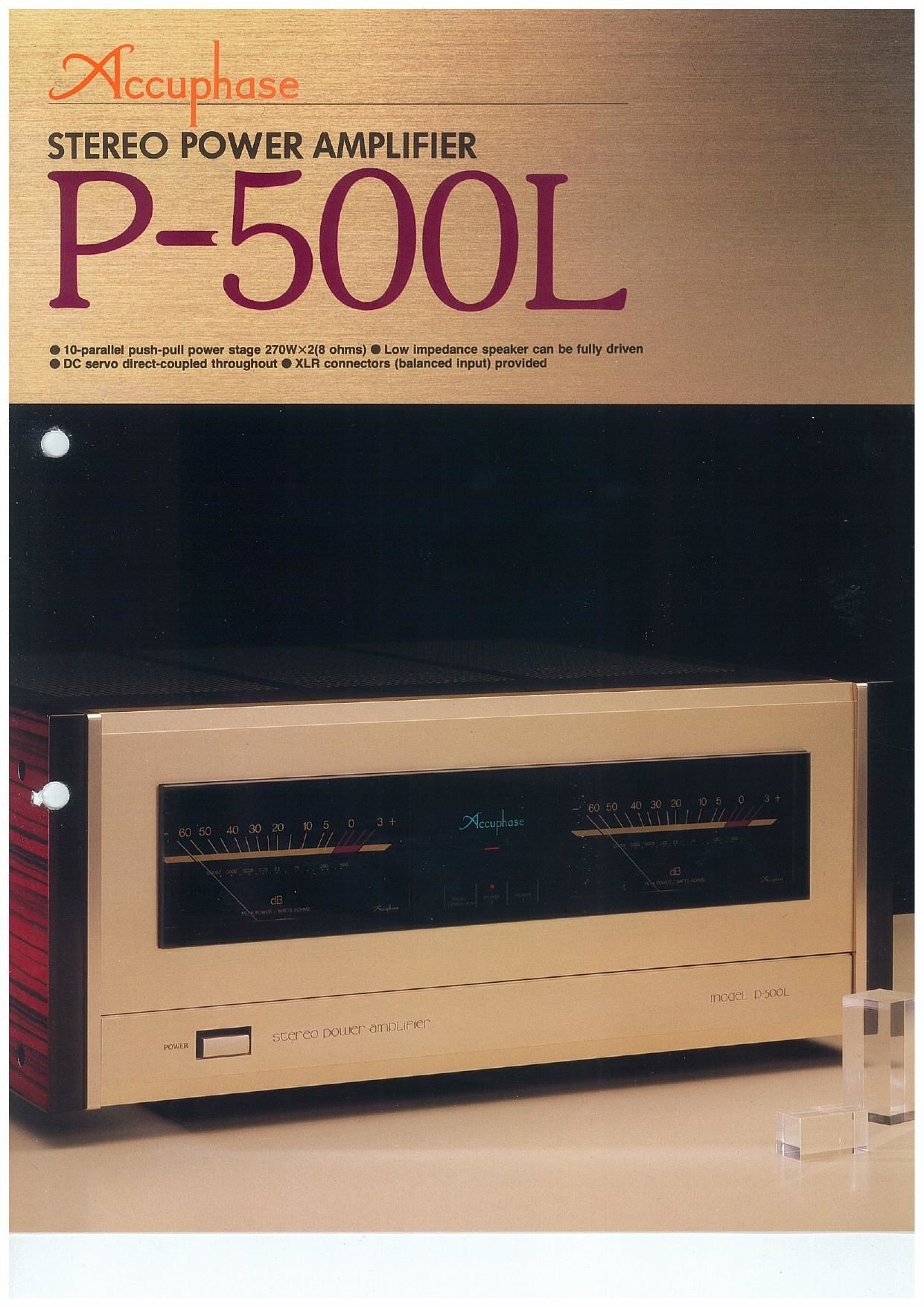
STEREO POWER AMPLIFIER
O 10«parallel push«pull power stage 270W><2(B ohms) 0 Low impedance speaker can be fully driven
0 DC servo direct-coupled throughout 0 XLR connectors (balanced Input) provided
Page 2
From the overwhelming impact of an orchestra
in full crescendo down to the breathless tension
ofadelicate pianissimo passage, all encompas-
sed in the ambience of the hall and the audi-
ence. such is the scope and excitement of live
music. In order to faithfully recreate this enorm~
ous dynamic range. to beautifully paint all de
tails of the musical "picture." an amplifier must
be capable of delivering ample energy levels
while at the same time maintaining fine resolu»
tion over the entire loudness spectrum. A large.
high
sure ample current and drive capability. This in
turn makes it possible to precisely control the
loudspeakers whose impedance varies consid-
erably depending on the frequency. However,
reproduction of very low-level signals. reaching
down to and even beyond the noise threshold, is
equally important. This is an area where conven-
tional high-power amplifiers often fall short.
The P~500L was designed to fulfill both of these
requirements perfectly. It belongs to a new am-
plifier breed which fully reflects the advanced
technological know-how incorporated in the top-
of-the-range models Accuphase MI 000 and P-
800. A powersupply with low output impedance.
high efficiency and large capacity forms the
basis of the P-500Ls solid performance. In each
channel of the output stage. ten wide-band
transistor pairs with a high power dissipation
(Pc) of 150 watts per device are used in a
parallel pushvpull configuration. resulting in a
total power dissipation of an amazing 3 kilowatts
per channel. This manifests itself in the output
rating of 550 watts per channel into 2 ohms. 420
watts into 4 ohms and 270 watts into 8 ohms. To
obtain even higher power levels, the amplifier
can be driven in bridged operation at the simple
flick of a switch. resulting in 1.100 watts into 4
ohms and 840 watts into 8 ohms. In bridged
mode. the amplifier is totally balanced for ulti-
mate operation characteristics.
The drive stage features the sophisticated MOS-
FET cascode push-pull design developed by
Accuphase. and a push-pull differential input
stage further increases sonic and electrical pre-
cision. Large power meters arranged symmetri-
cally on the front panel and the traditional
Accuphase styling in champagne gold comple-
ment an amplifier which is not only an exhilarat-
ing listening experience but also a delight to look
at and a lasting joy to own.
-INPUT
+INPUT
parallel push-pull lranslstor pairs
dellvers 550 watts per channel into 2
ohms, 420 watts into 4 ohms and 210
watts Into 8 ohms
Fig. 1 shows a circuit diagram of the P-500L. In
order to drive the loudspeakers with optimum
precision. the output impedance of an amplifier
should be as low as possible. By using large
amounts of negative feedback (NFB), impe-
dance ratings can be lowered quite impressive-
ly on paper. but this approach does not result in
the kind of sonic performance Accuphase is
famous for. Therefore the P-500L employs a total
of ten transistor pairs connected in parallel.
which lowers the output impedance to one-tenth
of each single device. The use of transistors with
high power dissipation (150 watts each. total
3.000 watts) further reduces the output impe»
dance. Even under very difficult load conditions.
such as when driving speakers with highly irre»
gular impedance curves. the P-SOOL performs
absolutely stable and delivers precisely the re-
quired amount of energy. This no-holds-barred
design lets the amplifier handle any real»life
application with ease. Current capability is out»
standing, as illustrated by the rating of 550 watts
per channel into 2 ohms.
Bridged operation mode creates a
balanced monophonlc ampllfler wlth
1,100 watts Into 4 ohms and 840
watts Into 8 ohms
By driving its two amplifiers in a symmetrical
configuration. the already impressive output
power of the P-500L can be further increased.
This is called bridged operation. The principle is
shown in Fig. 2. An identical signal with opposite
phase is fed to the input of each stage. resulting
in two output signals of opposite phase. which
form an ideal balanced amplifierwith double the
output power. In this type of application. consid-
erable demands are placed on the load handl-
ing capacity of the amplifier. When for example
an 8-ohm speaker is connected. each of the
amplifier stages actually "sees" a 4-ohm load
impedance. Therefore the circuit ratings and
current capability must be up to this task. In the
P»500L. the extraordinary potent output stage
with its ten parallel push-pull transistor pairs
ensures total operation safety. and a switch
makes it easy to access bridged operation. In
conventional designs. the input of one amplifier
section has a phase inverter circuit which can
1 Powerful output stage with 10
Flg. 1 P-500L Clrcult Diagram
detract from signal purity. In the P-500L. the
polarity of the differential input circuits is used in
an ingenious design. permitting a simple switch-
ing arrangement without the need for any addi-
tional amplifier stages.
Cascade push-pull + MOS FET
oesoode push-pull" drlve stage for
minimum dlstonlon at low levels and
superior high-range stabillty
The dynamic impact of an orchestra playing at
resounding levels and the minute detail of a
delicate pianissimo passage-both of these as-
pects are essential for true music reproduction.
With conventional high-power amplifiers. per-
formance at low levels often leaves much to be
desired. Not so in the case of Accuphase com-
ponents. which are built to deliver utterly cone
vincing performance at both ends of the loud,
ness spectrum.
In the output stage. the operating points of the
PNP and NPN transistors are carefully adjus' \
so as to avoid cutoff (current flow interruptioa}
thereby eliminating switching distortion at low
signal levels. The final predriver stage employs
MOS-FET devices (0.3. Q...) in an arrangement
which is equivalent to non-switching class A
drive. Cascode push-pull topology further im-
proves performance.
The devices Q. 015 and Q. Q... in Fig. 1 form
the casoode connection. This principle was
originally developed for radio-frequency ampli-
fication. It guarantees stable operation over a
wide range. resulting in outstanding input linear-
ity and wide dynamic range. The drive current
for this stage is supplied by another class A
cascode push-pull arrangement. The overall re-
sult of this approach is absolutely negligible
distortion and totally stable operation. from the
noise threshold up to full rated power. under any
load condition.
Cascade dltlerentlal push-pull Input
stage turned for pertectlon
In order to make full use of the performance
capabilities of the balanced output circuits. t
amplifier's input stage must also conformwJ
highest quality standards. To achieve this ai .
all Accuphase power amplifiers use a class A
cascode differential push-pull circuit configura-
tion in the input stage. High-frequency phase
characteristics are outstanding. and dynamic
range is significantly improved.